Moving magnet actuator

a magnet actuator and moving magnet technology, applied in the field of magnet actuators, can solve the problems of not scaling up the known magnetic actuator, too large known magnetic actuator,

Active Publication Date: 2008-01-15
IMMERSION CORPORATION
View PDF10 Cites 69 Cited by
  • Summary
  • Abstract
  • Description
  • Claims
  • Application Information

AI Technical Summary

Problems solved by technology

Known magnetic actuators often are too large for the volume constraints in, for example, touch panel applications.
Known magnetic actuators are also often not scaleable (i.e., different designs are needed depending upon the particular application).

Method used


Image

  • Moving magnet actuator
  • Moving magnet actuator
  • Moving magnet actuator

Examples


Embodiment Construction

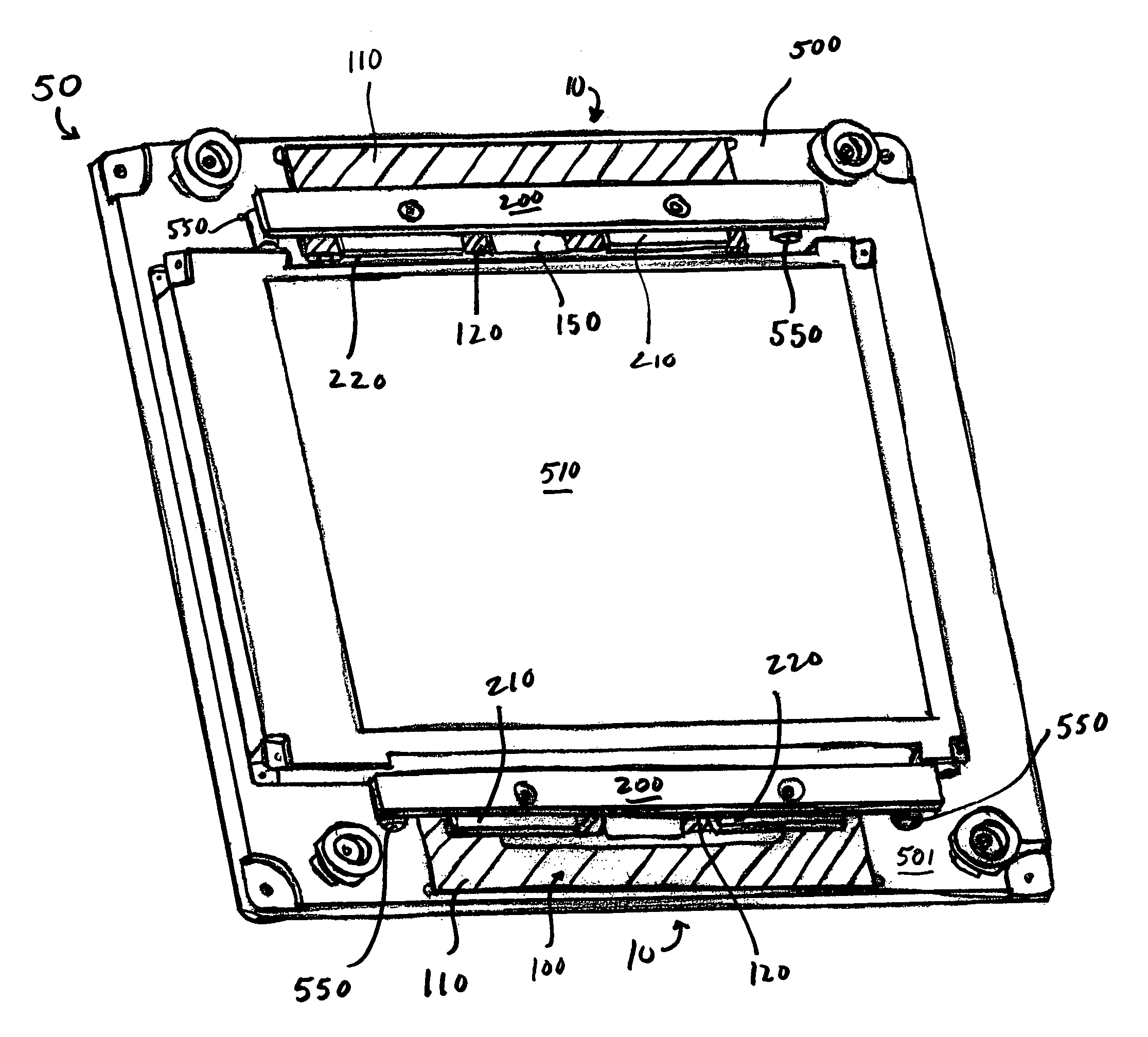
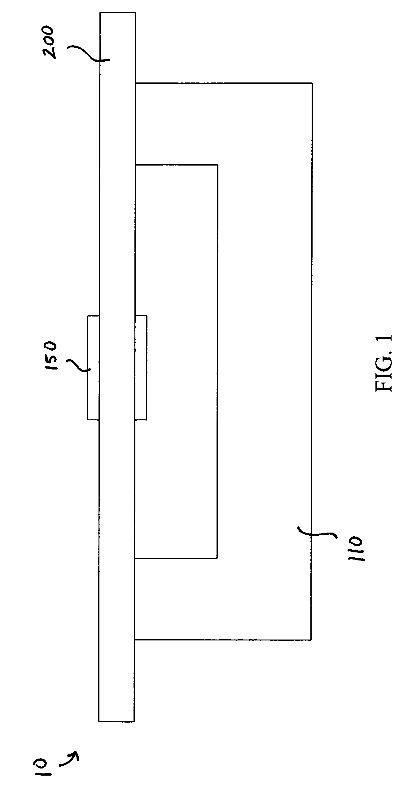
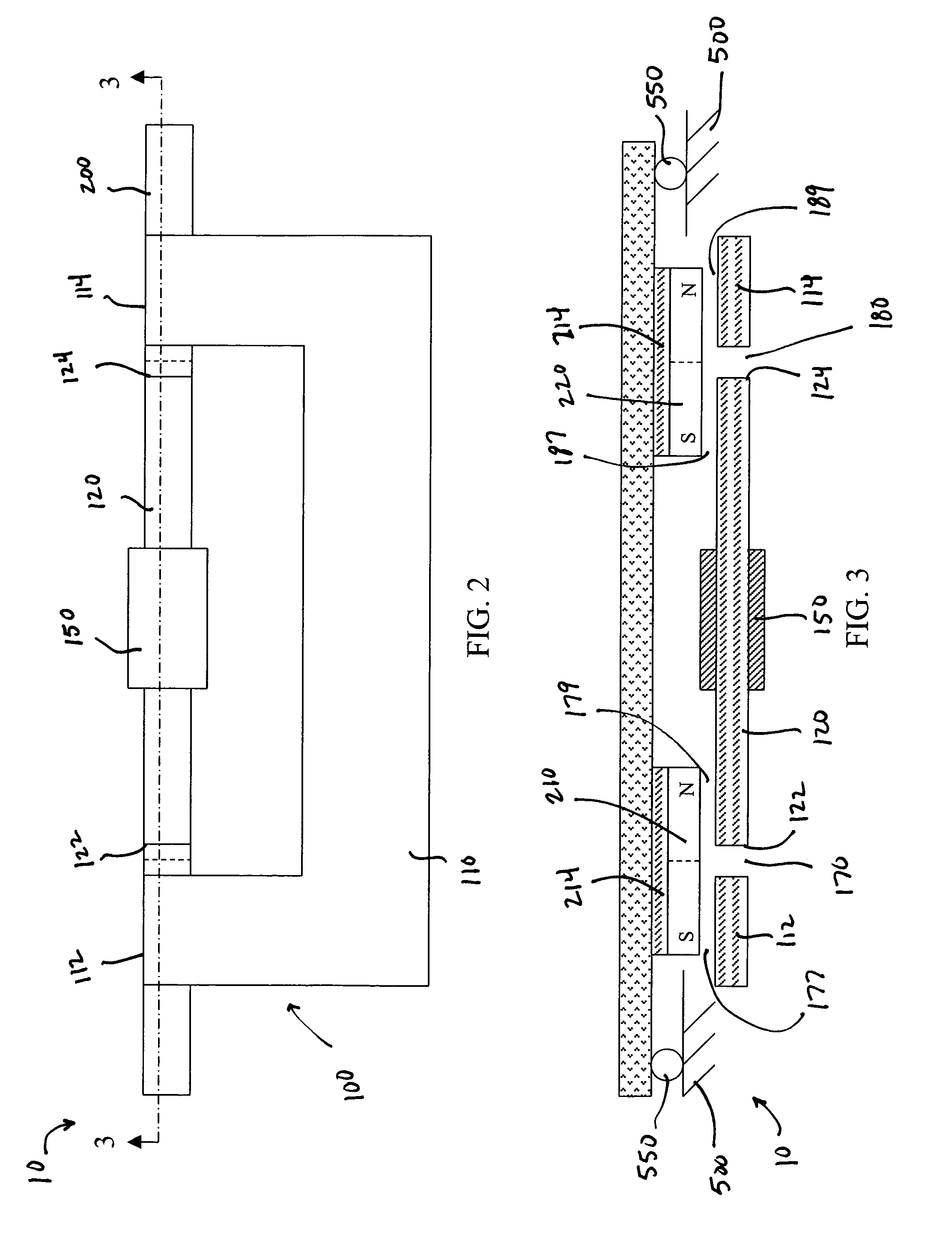
[0021]Referring to FIGS. 1-4, an actuator 10 for use in an interface device 50 according to an embodiment of the invention is illustrated. The actuator 10 includes an electromagnetically conductive assembly 100 that is substantially planar in configuration. A movable member 200 is coupled opposite the conductive assembly 100 and is configured to move with respect to the conductive assembly 100. The conductive assembly 100 includes a first member 110 having a first end 112 and a second end 114, and a second member 120 having a first end 122 and a second end 124. The second member 120 is disposed between the first end 112 and the second end 114 of the first member 110 as best seen in FIG. 2.

[0022]In some embodiments, the first member 110 and the second member 120 are physically distinct from one another. In other words, the first member 110 and the second member 120 are separate pieces that are not joined together. In some embodiments of the invention, the first member 110 and the sec...


PUM


Abstract

An apparatus includes an electromagnetically conductive assembly including a first member having a first end and a second end and a second member disposed between the first end and the second end of the first member. The second member and the first end of the first member define a first gap. The second member and the second end of the first member define a second gap. A movable member moves with respect to the conductive member. A first magnet is coupled to the movable member and is disposed a distance from the first gap. A second magnet is coupled to the movable member and is disposed a distance from the second gap.

Description

CROSS-REFERENCE TO RELATED APPLICATION[0001]This application claims the benefit of U.S. Patent Application No. 60 / 561,917, entitled “Haptic Touch Screens,” filed on Apr. 14, 2004, the entirety of which is incorporated herein by reference.BACKGROUND[0002]The invention relates generally to magnetic actuators for haptic feedback interface devices, and more particularly to magnetic actuators having multiple poles and multiple magnets.[0003]Haptic feedback interface devices are used for a variety of different functions and are often used with a variety of systems. For example, haptic feedback interface devices are used with computer controlled simulations, games, and other application programs. A computer system typically displays a graphical environment to a user on a display screen or other output device. The user can interact with the displayed environment to play a game, experience a simulation or “virtual reality” environment, or otherwise influence events or images depicted on the ...

Claims


Application Information

Patent Timeline
Patent Type & Authority Patents(United States)
IPC IPC(8): H01F7/08H01F7/122H01F7/16H02K33/16
CPCH01F7/16H02K33/16H01F7/122H01F7/1646
Inventor SHAHOIAN, ERIK J.
Owner IMMERSION CORPORATION
Why Eureka
Try Eureka