
Three-axis offset damping system

Inactive Publication Date: 2008-01-22
LOCKHEED MARTIN CORP
View PDF11 Cites 15 Cited by
  • Summary
  • Abstract
  • Description
  • Claims
  • Application Information

AI Technical Summary

Benefits of technology

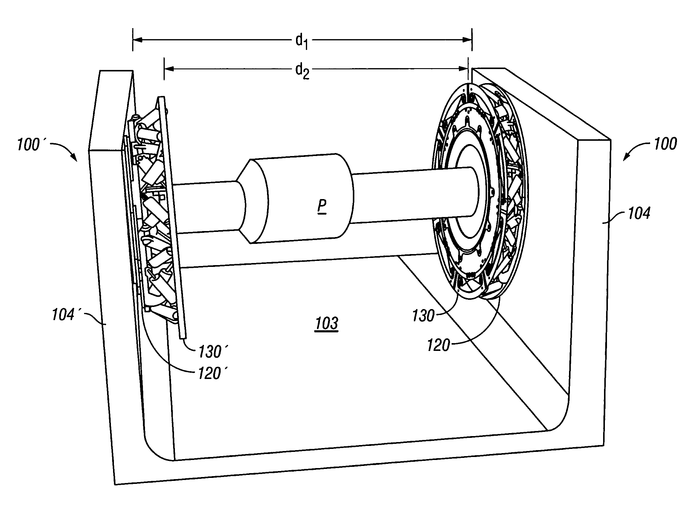
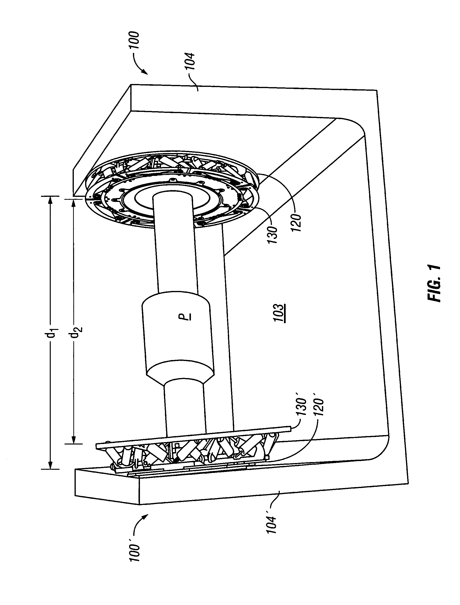
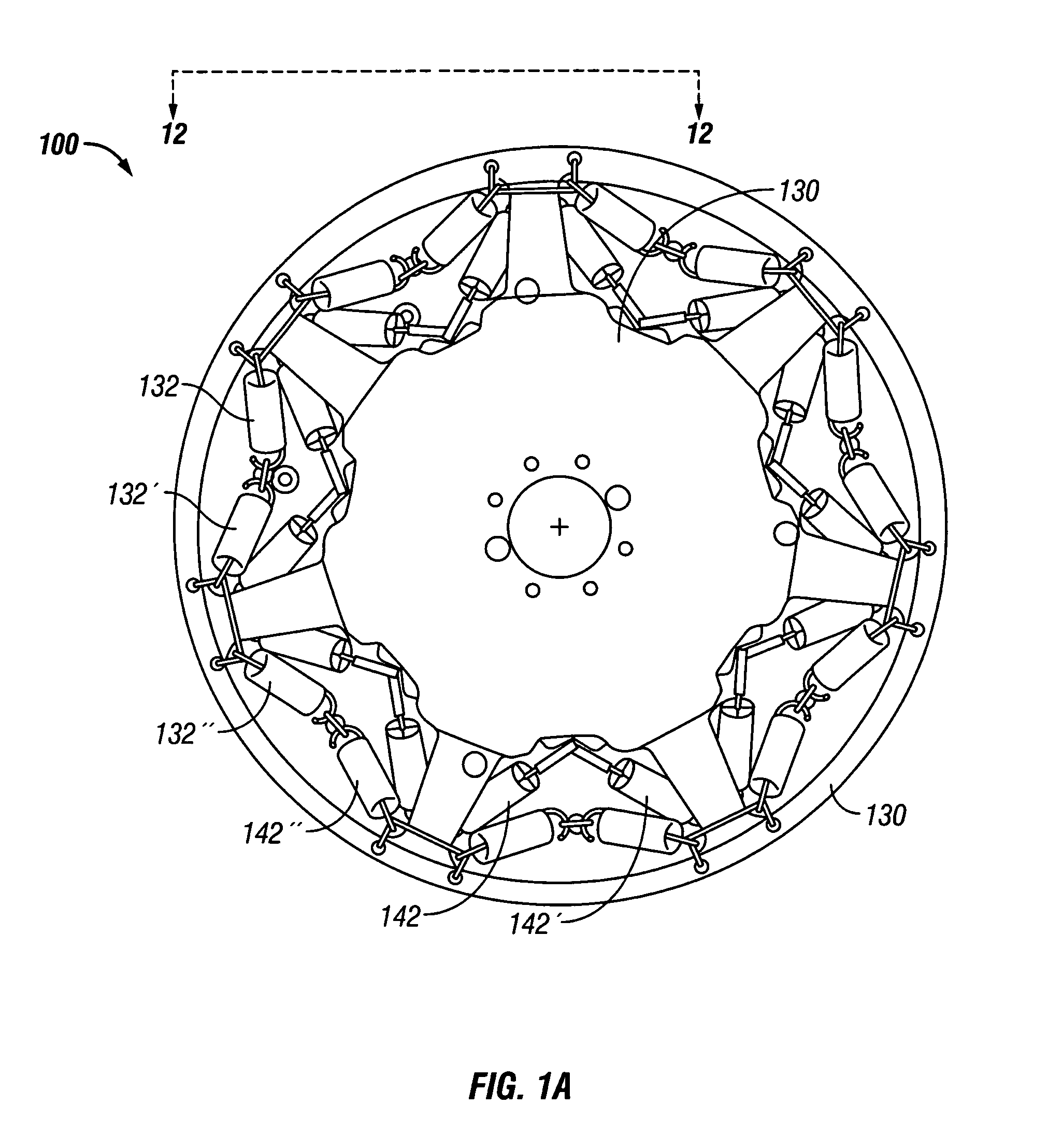
[0012]The difference of the distance between the outer isolator plates and the distance between the inner isolator plates divided by a factor of two may be approximately equal to the distance between each outer isolator plate and each adjacent inner isolator plate. The separation of the yoke arms holds the outer isolator plates apart from the inner isolator plates connected to the object to be protected so that the tension of the springs is set. The springs and the dampers are arranged to insulate the inner isolation plates from movement of said outer isolation plates. The dampers ameliorate the rebound effects of the springs.

Problems solved by technology

The rapid accelerations resulting from abrupt changes in speed and / or direction of movement may adversely affect the performance of, or even damage, certain critical devices or systems.
Standard spring-biased systems, however, typically offer little or no damping.
Such systems are not adequate in, for example, harsh military environments, where it is difficult to control the isolated mass of the sensor.
These known devices perform satisfactorily generally only in thermally stable environments.
Further, known rubber damper devices have limited capabilities when sway space is at a premium or minimal.
Known rubber isolator devices are inadequate under such conditions.

Method used


Image

  • Three-axis offset damping system
  • Three-axis offset damping system
  • Three-axis offset damping system

Examples


example 1

[0091]A three-axis offset damping system was constructed generally in accordance with the foregoing description. The hydraulic dampers contained 80-weight oil in one example, or 50-weight oil in another example. The payload weighed approximately 84.1 lbs. The system was subjected to a randomly selected one of a series of controlled vibratory environmental conditions, and the system response was measured. The drawing figures described below thus pertain to only one of a vast set of possible environmental vibratory conditions and are offered only by way of example to demonstrate the effectiveness of the invention.

[0092]FIG. 14 is a table setting forth the response of the system in the vertical, longitudinal, and lateral axes, by natural frequency and damping percent, at 6 db transmissibility and either 50 W or 80 W oil in the dampers. A “control” was run using only extension springs, without any dampers. Combined reference to FIGS. 14-17 shows marked improvement in system response wit...


PUM


Abstract

The present invention comprises a three-axis damping system employing dampers and springs in spatially oriented arrays to isolate an object against translational forces in any direction as well as rotational forces. The inventive system also is biased in the vertical static position to compensate for gravity.

Description

CROSS-REFERENCE TO RELATED APPLICATIONS[0001]This application claims the benefit of the filing of U.S. Provisional Patent Application Ser. No. 60 / 460,281, entitled “Three-Axis Offset Damping System,” filed on Apr. 3, 2003, and the specification thereof is incorporated herein by reference.GOVERNMENT RIGHTS[0002]The U.S. Government has certain rights to this application and invention pursuant to the terms of Contract No. N-000-19-96C-0128 awarded by the United States NavyBACKGROUND OF THE INVENTION[0003]1. Field of the Invention (Technical Field)[0004]The present invention relates to an apparatus for physically isolating delicate or sensitive instrumentation systems, particularly to a damping apparatus for isolating items or systems from abrupt and potentially destructive accelerations.[0005]2. Background Art[0006]There are a variety of contexts in which it is desirable to physically isolate items against potentially destructive movements, particularly rapid accelerations. For example...

Claims


Application Information

Patent Timeline
IPC IPC(8): F16F7/10
CPCF16F15/022
Inventor MYERS, JAMES R.GRAVES, ROGER W.GO, GEORGEHIGGINS, THOMAS E.
Owner LOCKHEED MARTIN CORP
Learn More