System and method of providing hydraulic pressure for mechanical work from an engine lubricating system

a technology of hydraulic pressure and mechanical work, applied in the direction of auxillary lubrication, non-mechanical valves, piston pumps, etc., can solve the problem that the system does not provide engine lubrication

Inactive Publication Date: 2008-01-29
BORGWARNER INC
View PDF19 Cites 14 Cited by
  • Summary
  • Abstract
  • Description
  • Claims
  • Application Information

AI Technical Summary

Problems solved by technology

The loads on the system are for hydraulic pistons and not continuous flow devices, such as motors, and the system does not provide engine lubrication.

Method used


Image

  • System and method of providing hydraulic pressure for mechanical work from an engine lubricating system
  • System and method of providing hydraulic pressure for mechanical work from an engine lubricating system
  • System and method of providing hydraulic pressure for mechanical work from an engine lubricating system

Examples


Embodiment Construction

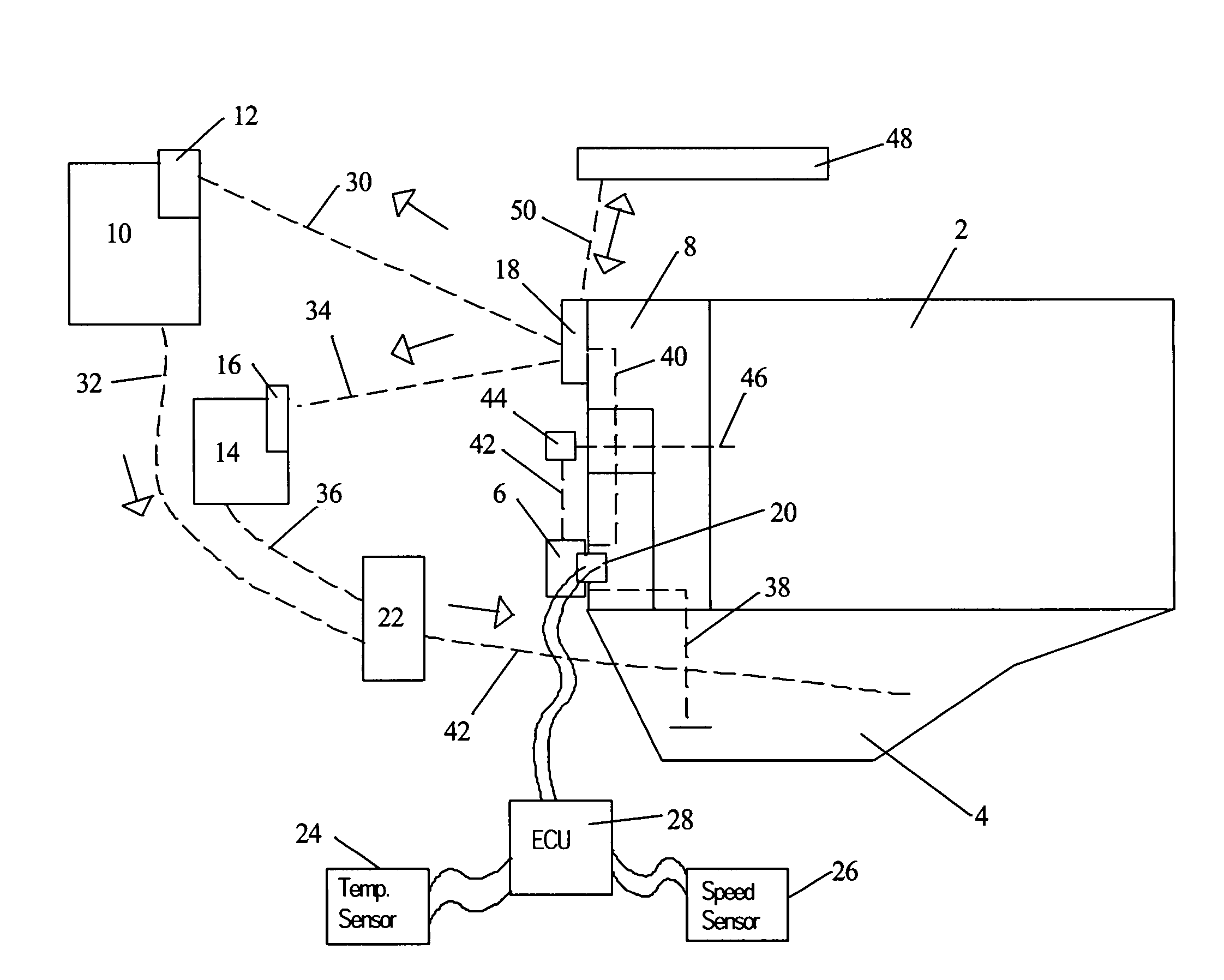
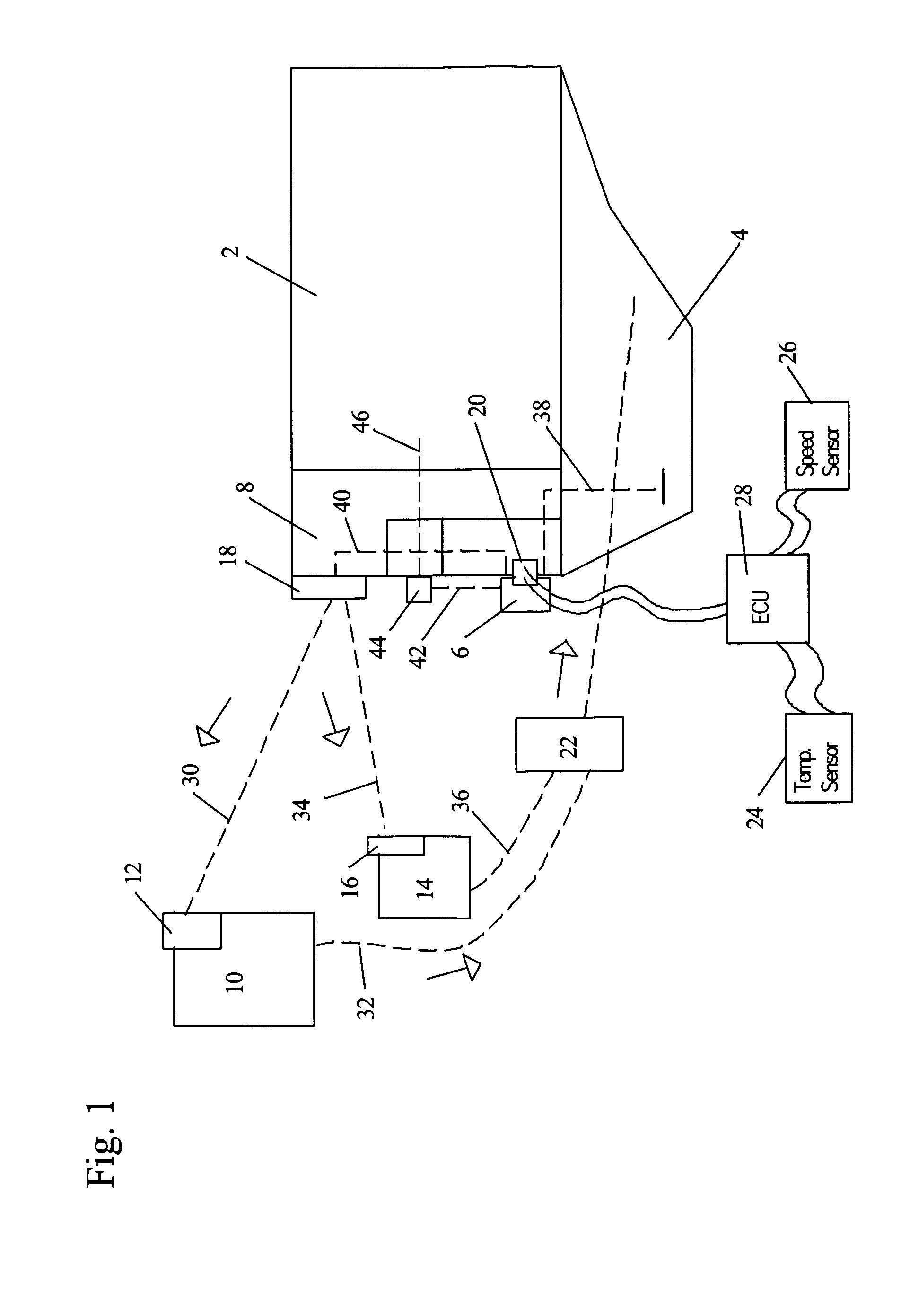
[0025]Referring to FIG. 1, mounted to the front cover 8 of the engine block 2 is a variable displacement pump 6 and a variable displacement pump controller 20. Although the variable displacement pump is shown in FIG. 1 as mounted to the front cover of the engine block, it may be mounted in other places near the engine block. Below the engine block 2 is a sump or oil pan 4. Also preferably connected to the front cover 8 of the engine block 2 is a high-pressure manifold 18.

[0026]The variable displacement pump 6 is preferably driven by a conventional valve chain, gear, or belt (not shown). A fluid line 38 connects the variable displacement pump 6 to the sump 4. A second fluid line 40 passes though the front cover 8 of the engine block 2 and connects the variable displacement pump 6 to the high-pressure manifold 18. The high-pressure manifold 18 may be incorporated into the front cover or completely separate and external. The variable displacement pump 6 is regulated by the variable dis...


PUM


Abstract

The method provides hydraulic pressure for mechanical work from an engine lubricating system in an internal combustion engine by supplying oil to an engine lubrication gallery for lubricating the engine and to at least one variable oil demand accessory. Each of the variable oil demand accessories has an individual pressure regulator. The output of the variable displacement pump is regulated based on the sum of fluid flow required by the engine lubricating system and the engine accessories, regardless of the engine output. The demand for fluid is determined by the individual pressure regulators on each of the engine accessories. In a preferred embodiment, an accumulator stores high-pressure fluid to be used to power the hydraulic accessories.

Description

REFERENCE TO RELATED APPLICATIONS[0001]This is a continuation-in-part patent application of application Ser. No. 10 / 826,104, filed Apr. 16, 2004 now U.S. Pat. No. 6,889,634, entitled “METHOD OF PROVIDING HYDRAULIC PRESSURE FOR MECHANICAL WORK FROM AN ENGINE LUBRICATING SYSTEM”. The aforementioned application is hereby incorporated herein by reference.BACKGROUND OF THE INVENTION[0002]1. Field of the Invention[0003]The invention pertains to the field of engine lubricating systems. More particularly, the invention pertains to a method of providing hydraulic pressure for mechanical work from an engine lubricating system.[0004]2. Description of Related Art[0005]Conventionally, accessories in cars (e.g. cooling fan, power steering system, A / C compressor, engine coolant pump, supercharger, and alternator) are powered using separate engine driven, fixed displacement pumps, or by direct drive, where the individual power demands of the accessories are not well matched to engine speed.[0006]So...

Claims


Application Information

Patent Timeline
Patent Type & Authority Patents(United States)
IPC IPC(8): F04B17/00F04B35/00F01M1/02F01M1/16F01M11/02F15B1/02F15B21/14
CPCF01M1/02F01M1/16F15B21/14F01M2011/021F15B2211/20523F15B2211/20546F15B2211/212F15B2211/633F15B2211/6343F15B2211/6654F15B2211/88
Inventor ROTH, DAVID B
Owner BORGWARNER INC
Why Eureka
Try Eureka