

Connecting device
a technology of connecting device and connector, applied in the direction of coupling device connection, optical element, instrument, etc., can solve the problems of preventing customer selection of a particular orientation, affecting the quality of the connection, and unable to change the keying arrangement, so as to prevent the inability to fix the plug or the location
- Summary
- Abstract
- Description
- Claims
- Application Information
AI Technical Summary
Benefits of technology
Problems solved by technology
Method used
Image

Examples
Embodiment Construction
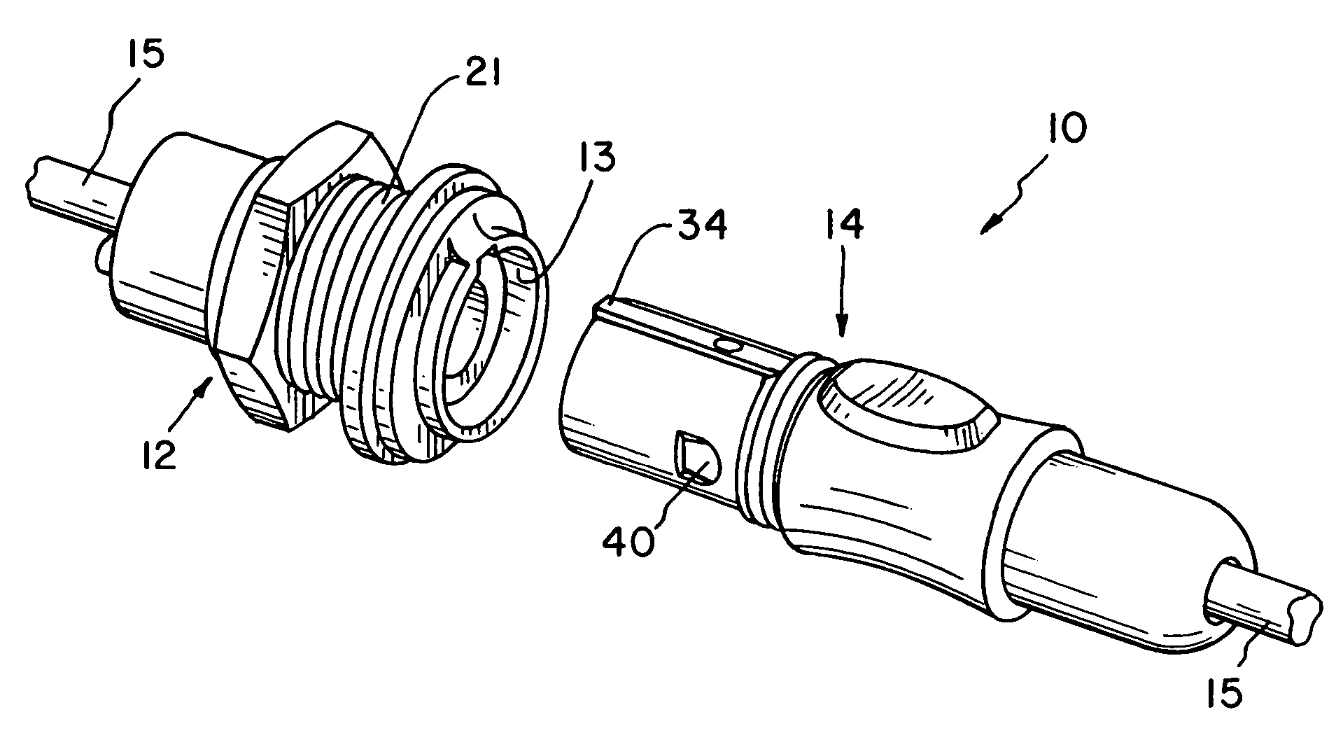
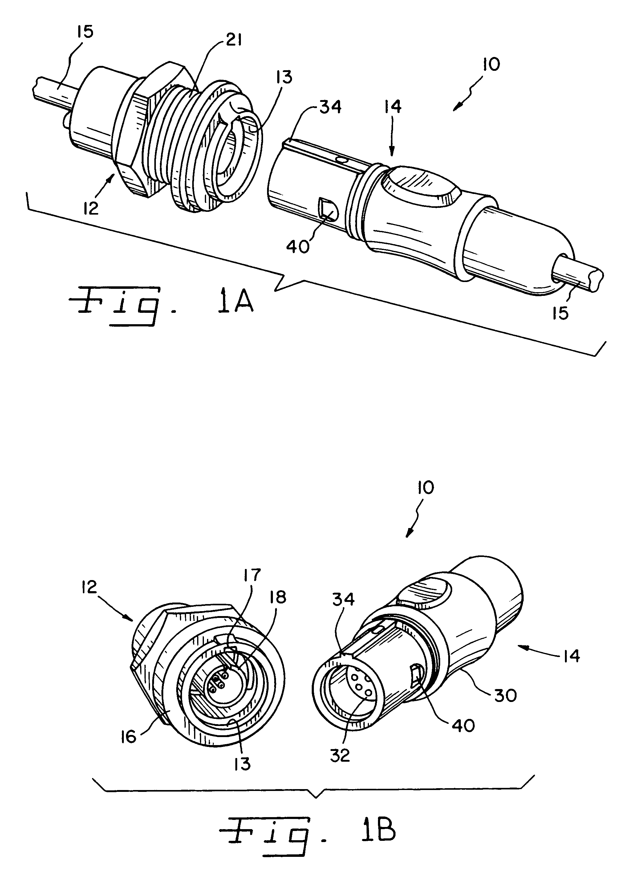
[0035]FIG. 1A shows connector assembly 10 of the present invention. FIG. 1A utilizes receptacle assembly 12 and plug assembly 14 which are interfit to make a connection between to electrical or optical conduits or cables 15. The style of connector assembly 10 is that of a push-pull connection, although alternate styles may be utilized.
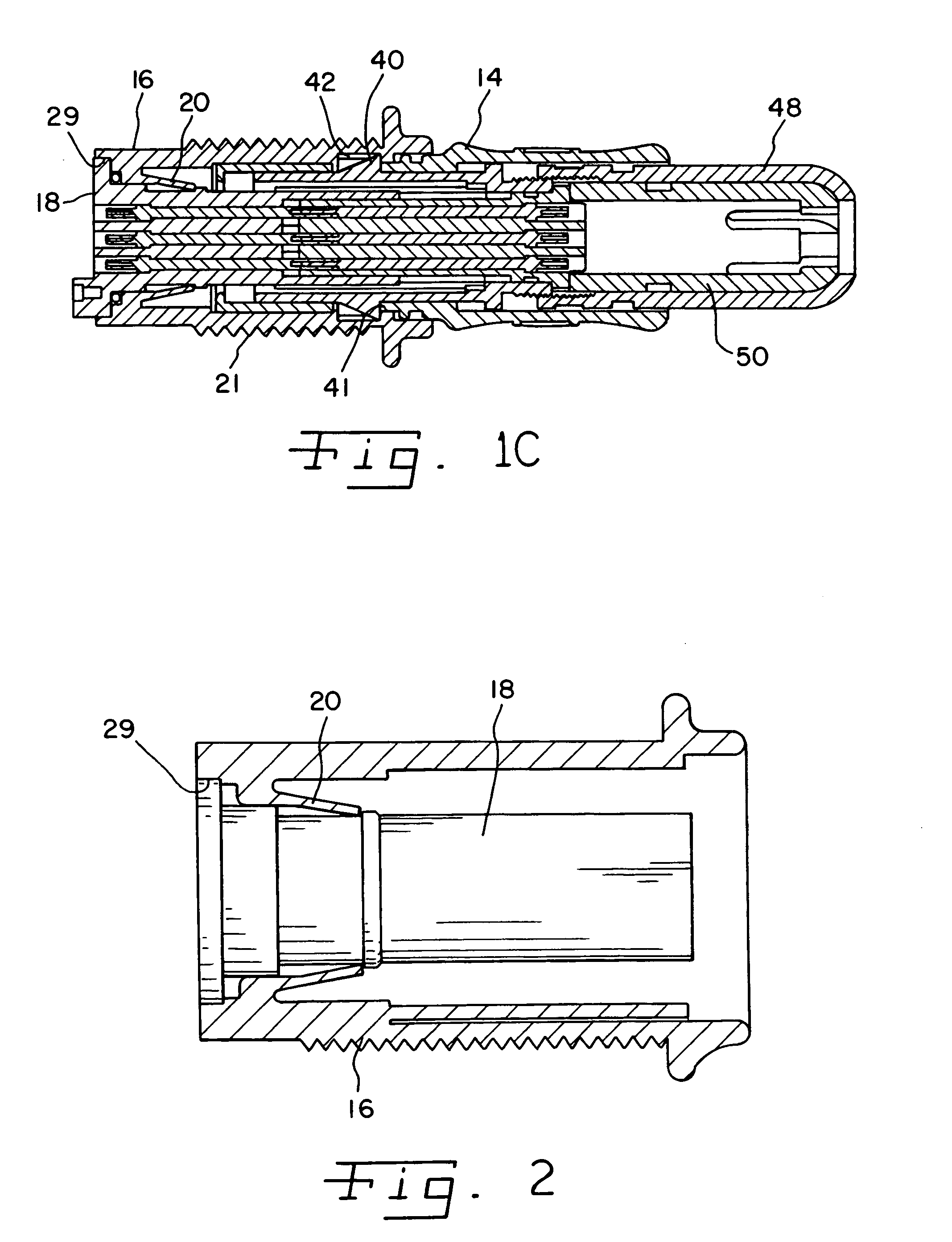
[0036]In FIG. 1B, receptacle assembly 12 is shown with an interfit receptacle insulator 18, later described. Plug assembly 14 as shown in FIG. 1B includes a plug case 30 having an interfit plug insulator 32. Plug case 30 includes a key 34 that slides into a corresponding groove 17 in receptacle case 16. This key 34 and groove 17 create and guide the relative orientation of the receptacle case 16 and plug case 30 when the connector assemblies are interfit. Also shown in FIG. 1C, emerging from plug case 30 is one of two radially opposed catches or ears 40 that interfit within a port or opening 42 within receptacle case 16.
[0037]Directing attention now to...
PUM
 Abstract
Description
Claims
Application Information