Modular plug with slider latch

a technology of modular plugs and latches, applied in the field of modular plugs, can solve the problems of modular plugs snagging and/or getting caught on adjacent modular plugs, and the latching mechanism is greatly hindered and impaired

Inactive Publication Date: 2008-02-12
COMMSCOPE TECH LLC
View PDF27 Cites 161 Cited by
  • Summary
  • Abstract
  • Description
  • Claims
  • Application Information

AI Technical Summary

Problems solved by technology

In densely packed arrays of receptacles, manipulation of the latching mechanism, for the modular plugs connected to substantially the centrally located receptacles of the array, is greatly hindered and impaired as compared to manipulation of the latching mechanisms for modular plugs located around the periphery of the array.
Additionally, at times, when unplugging and / or removing the modular plug from the receptacle array, the modular plug may snag and / or get caught on adjacent modular plugs or the like.

Method used


Image

  • Modular plug with slider latch
  • Modular plug with slider latch
  • Modular plug with slider latch

Examples


Embodiment Construction

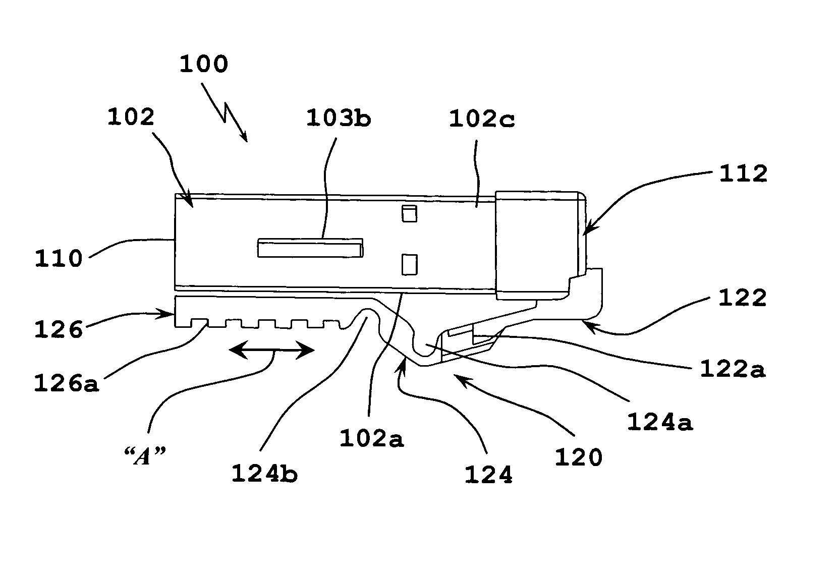
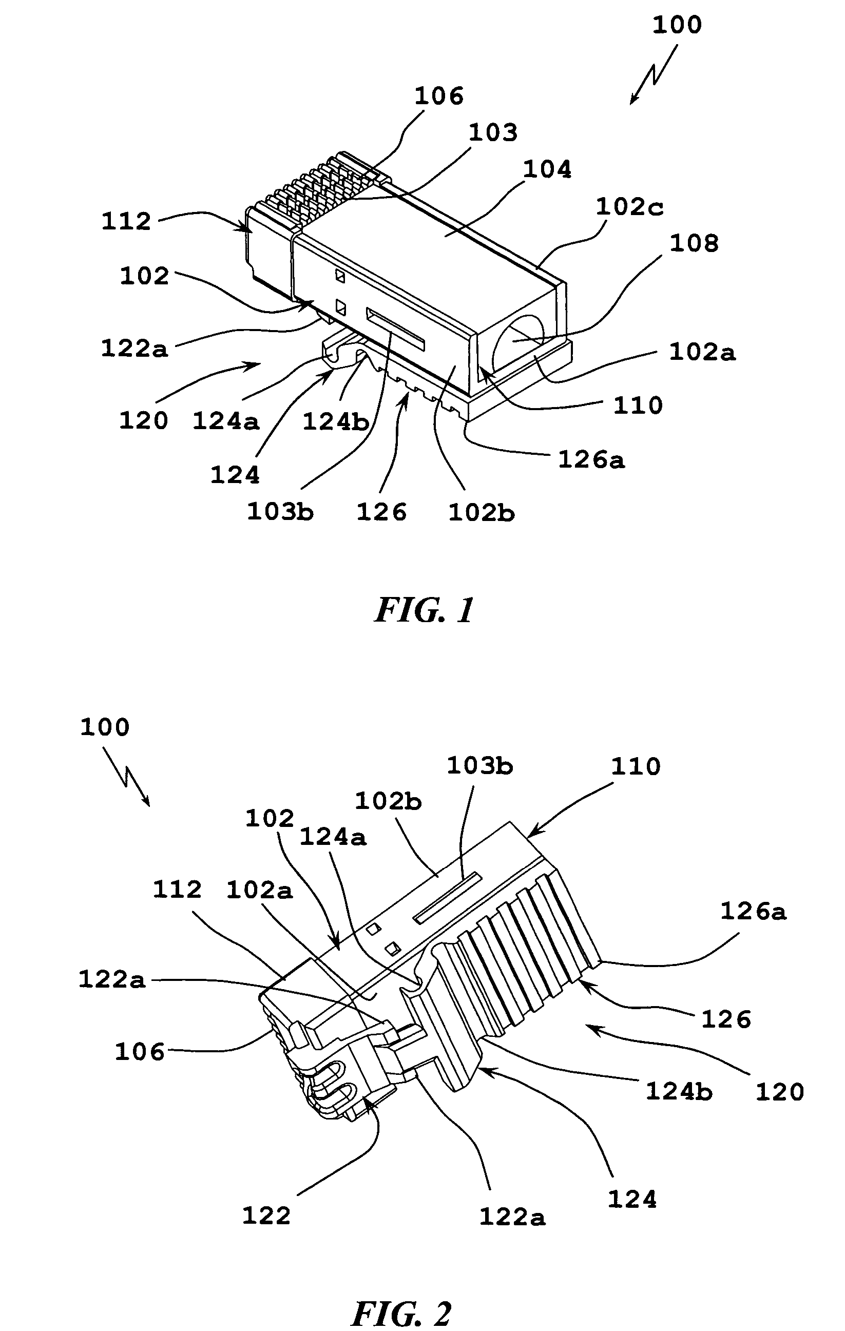
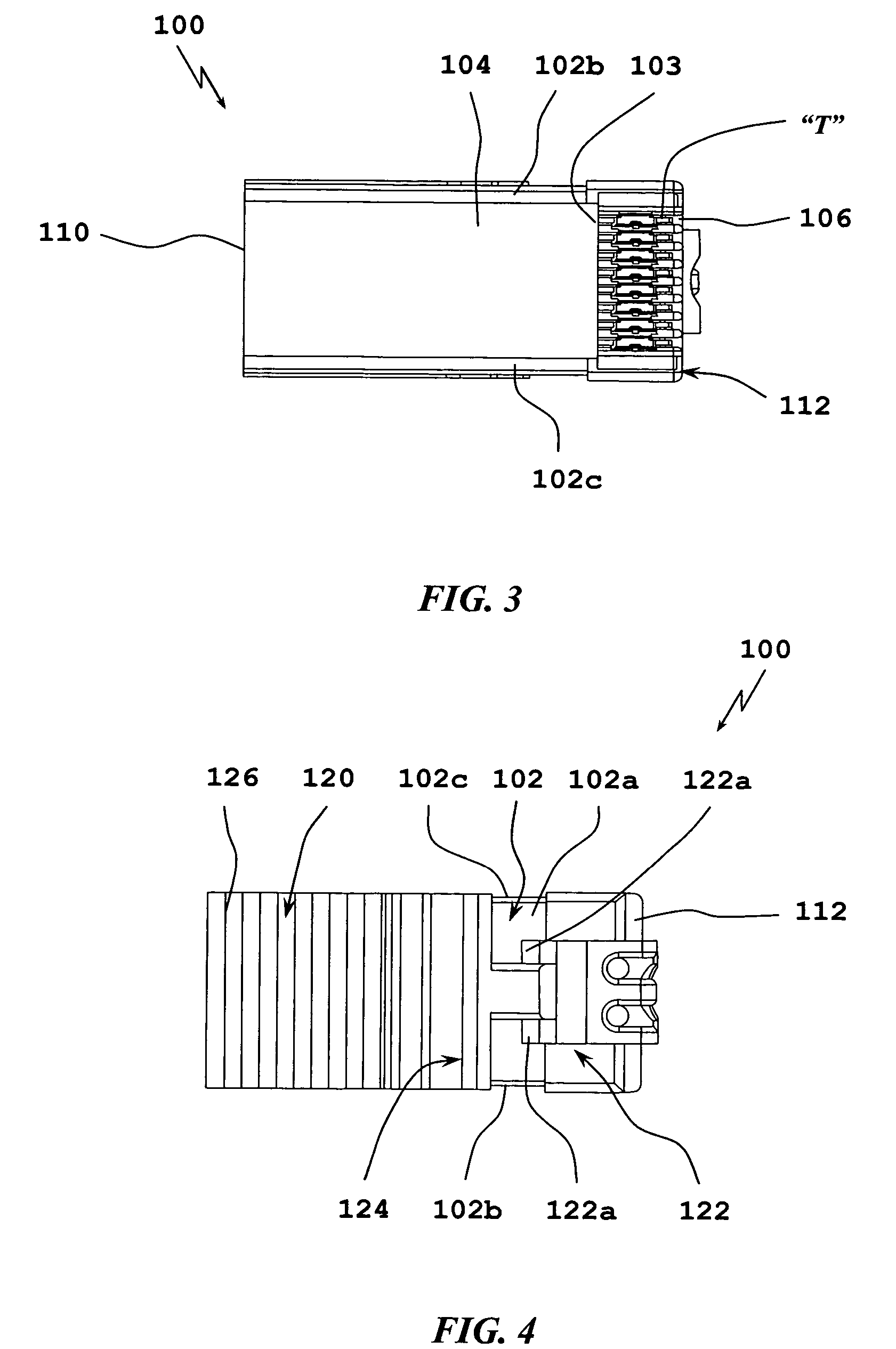
[0041]Embodiments of the presently disclosed modular plugs will now be described in detail with reference to the drawing figures wherein like reference numerals identify similar or identical elements. As used herein and as is traditional, the term “distal” refers to that portion which is furthest from the user while the term “proximal” refers to that portion which is closest to the user. In addition, terms such as “above”, “below”, “forward”, “rearward”, etc. refer to the orientation of the figures or the direction of components and are simply used for convenience of description.

[0042]Referring initially to FIGS. 1-12, a modular plug (e.g., electrical connector, data connector, telephonic connector, etc.), for selective connection to a complementary receptacle (not shown), is generally designated as 100. Modular plug 100 is matable with a plug receptacle 200 (see FIGS. 13-18) for interconnecting a plurality of wires (not shown) or the like. Modular plug 100, as described herein, is ...


PUM


Abstract

The present disclosure relates to modular plugs including a housing for holding a plurality of terminals that are engageable with contacts of a mating plug receptacle. The modular plug further includes a slider latch having a distal end portion integrally formed with the housing, a proximal end portion configured and adapted for operative engagement with the housing, and an intermediate portion disposed between the distal end portion and the proximal end portion. The intermediate portion defines at least one flex point. Accordingly, when the proximal end portion of the slider latch is operatively connected to the housing, the intermediate portion of the slider latch defines an anti-snag feature. The slider latch facilitates locking and unlocking of the modular plug with a plug receptacle when in a densely packed array.

Description

BACKGROUND[0001]1. Technical Field[0002]The present disclosure relates to modular plugs and, more particularly, to modular plugs including a slider latch capable of locking and un-locking the modular plug to a corresponding receptacle.[0003]2. Background of Related Art[0004]Modular plugs and modular jacks are commonly used for interconnecting a plurality of wires in communications systems. Various latching mechanisms and the like have been developed and incorporated into electrical, data and / or telephonic cable connectors or plugs for mechanically connecting the modular plug to a corresponding complementary receptacle. Typically, in order to release the plug from the receptacle an individual must squeeze, depress or otherwise manipulate the latching mechanism in order to release the modular plug from the receptacle.[0005]In densely packed arrays of receptacles, manipulation of the latching mechanism, for the modular plugs connected to substantially the centrally located receptacles ...

Claims


Application Information

Patent Timeline
Patent Type & Authority Patents(United States)
IPC IPC(8): H01R13/625
CPCH01R13/501H01R13/6272H01R13/633
Inventor MARTIN, RALPH SYKESDOOLEY, CHRISTINE A.
Owner COMMSCOPE TECH LLC
Why Eureka
Try Eureka