Self-adjusting strobe

a self-adjusting, strobe technology, applied in the direction of instruments, audible signalling systems, signalling systems, etc., can solve the problems of generating heat and requiring supplemental power supplies

Active Publication Date: 2008-02-19
HONEYWELL INT INC
View PDF10 Cites 1 Cited by
  • Summary
  • Abstract
  • Description
  • Claims
  • Application Information

AI Technical Summary

Problems solved by technology

Where numerous strobes are present in an alarm system current demands by such strobes which are often coupled to relatively long power supply lines can cause losses, generate heat, and require supplemental power supplies.

Method used


Image

  • Self-adjusting strobe
  • Self-adjusting strobe
  • Self-adjusting strobe

Examples


Embodiment Construction

[0010]While embodiments of this invention can take many different forms, specific embodiments thereof are shown in the drawings and will be described herein in detail with the understanding that the present disclosure is to be considered as an exemplification of the principles of the invention and is not intended to limit the invention to the specific embodiment illustrated.

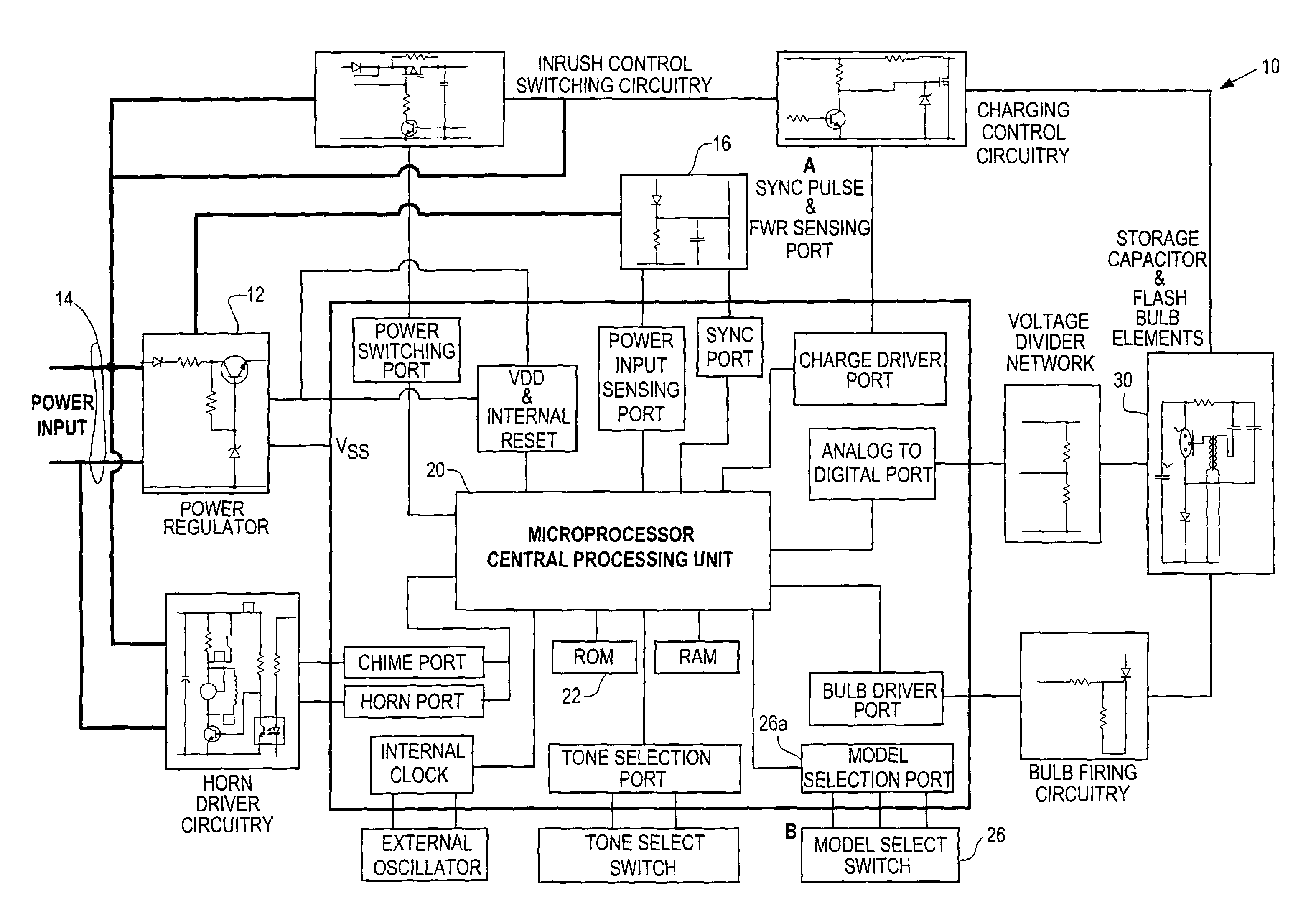
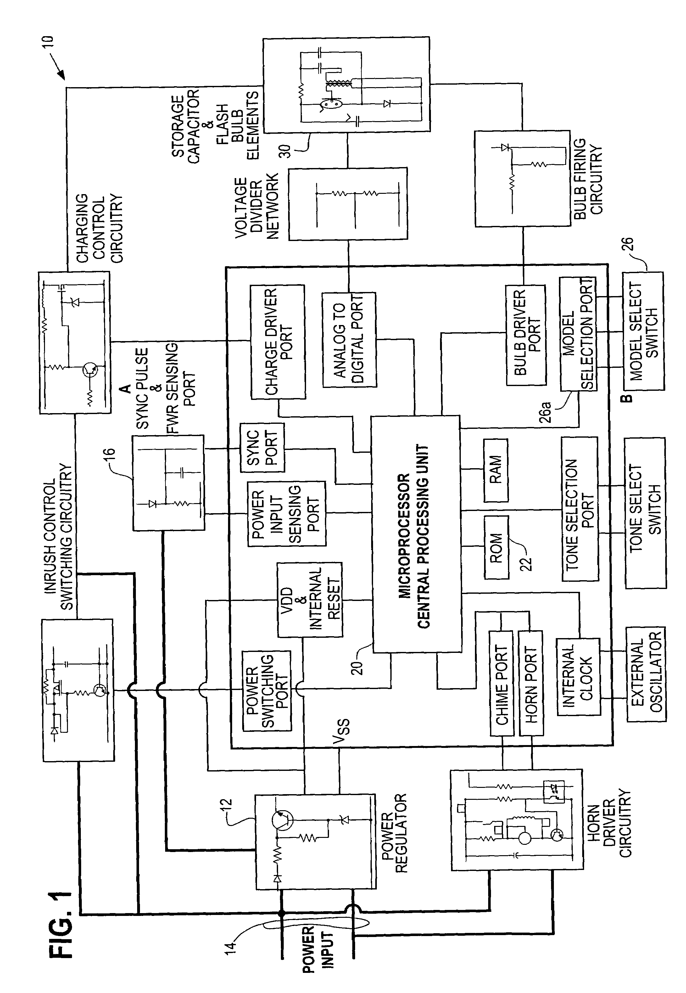
[0011]FIG. 1 illustrates a strobe unit 10 which incorporates a power regulator 12 for providing local unit power off of power input lines 14. Applied power from lines 14 could be DC power or could be full wave rectified. Circuitry 16 senses the presence of synchronizing pulses as well as senses the presence of full wave rectified input power.

[0012]Strobe unit 10 is controlled in an overall fashion by processor 20. Processor 20 in conjunction with a control program prestored in read only memory (EEPROM for example) 22 can carry out a plurality of functions including sensing selected output candela, via model selec...


PUM


Abstract

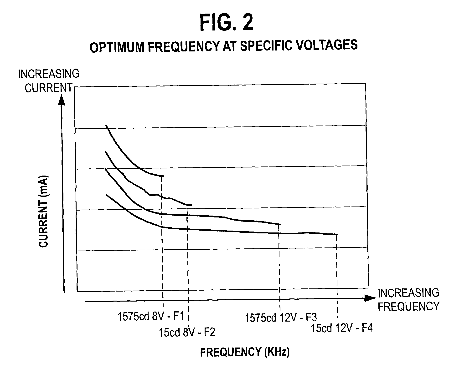
A strobe unit responds to a selected candela output by selecting an optimal capacitor charging frequency to minimize current requirements at the selected candela output. A plurality of charging frequencies can be stored and associated with available input power and selected candela output.

Description

FIELD OF THE INVENTION[0001]The invention pertains to strobe units that provide visible alarm indications. More particularly, the invention pertains to such units which alter internal operating parameters in response to externally related conditions.BACKGROUND OF THE INVENTION[0002]It has been know to use strobe units to provide pulses of visible light, as indicators of an alarm condition, in fire alarm systems and the like. One such strobe has been disclosed in Ha et al. U.S. patent application entitled “Processor Based Strobe with Feedback” application Ser. No. 10 / 444,227 filed May 23, 2003 and assigned to the Assignee hereof. The disclosure and figures of the '227 application are hereby incorporated herein by reference. U.S. Pat. No. 6,522,261 B2 entitled “Selectable Candela Strobe Unit” which issued Feb. 18, 2003 is assigned to the assignee hereof and is incorporated herein by reference. The '261 patent discloses strobes having variable candela output levels.[0003]Such units, as...

Claims


Application Information

Patent Timeline
Patent Type & Authority Patents(United States)
IPC IPC(8): G08B5/00H05B39/00H05B41/00
CPCH05B41/34
Inventor HA, SIMONASINJO, ROBERT
Owner HONEYWELL INT INC
Why Eureka
Try Eureka