System and method of increasing efficiency of heat pumps

a heat pump and efficiency technology, applied in the field of heating systems, can solve the problems of increasing the difficulty of the heat pump to extract heat from colder outdoor air, reducing efficiency, and preventing the heat pump's operation, and achieve the effect of increasing heating efficiency

Inactive Publication Date: 2008-03-11
THOMPSON THOMAS W
View PDF11 Cites 9 Cited by
  • Summary
  • Abstract
  • Description
  • Claims
  • Application Information

AI Technical Summary

Benefits of technology

[0022]By monitoring the indoor refrigerant coil temperature and the supply duct air temperature near the unit, the airflow can be adjusted to match the BTU (heat) output of the heat pump system. Less air flow over a cooler indoor refrigerant coil temperature allows increased, more efficient, heat transfer, allowing the cooler indoor refrigerant coil temperature to more effectively warm the air. Additionally, with the air flow reduced at times when the indoor refrigerant coil is operating at lower than optimal temperatures or during a defrost cycle, the reduced air flow into living spaces presents a less drafty condition, reducing or eliminating unpleasant effects of a cold blow and providing a more consistent comfort level.

Problems solved by technology

It can be readily recognized that, as outdoor temperatures drop, it becomes increasingly difficult for the heat pump to extract heat from colder outdoor air.
Thus, it is common, under certain operating conditions, for frost to form on the outdoor heat-exchanging coil, reducing efficiency and ultimately preventing the heat pump's operation if frost buildup is excessive.
During this reverse cycle, the indoor heat-exchanging coil is cooled, rather than heated, contributing to a cold blow.
The use of supplemental electric resistance heating elements, however, increases energy requirements for the system, resulting in a decrease in heating efficiency.
The heat pump is thus disabled when weather conditions do not favor efficient heat pump operation.
The system uses temperature sensors located variously within the living spaces to vary the fan motor speed during both heating and cooling operations, but does not measure the available heat output during heating operations to set the fan motor speed for optimal heat transfer.

Method used


Image

  • System and method of increasing efficiency of heat pumps
  • System and method of increasing efficiency of heat pumps
  • System and method of increasing efficiency of heat pumps

Examples


Embodiment Construction

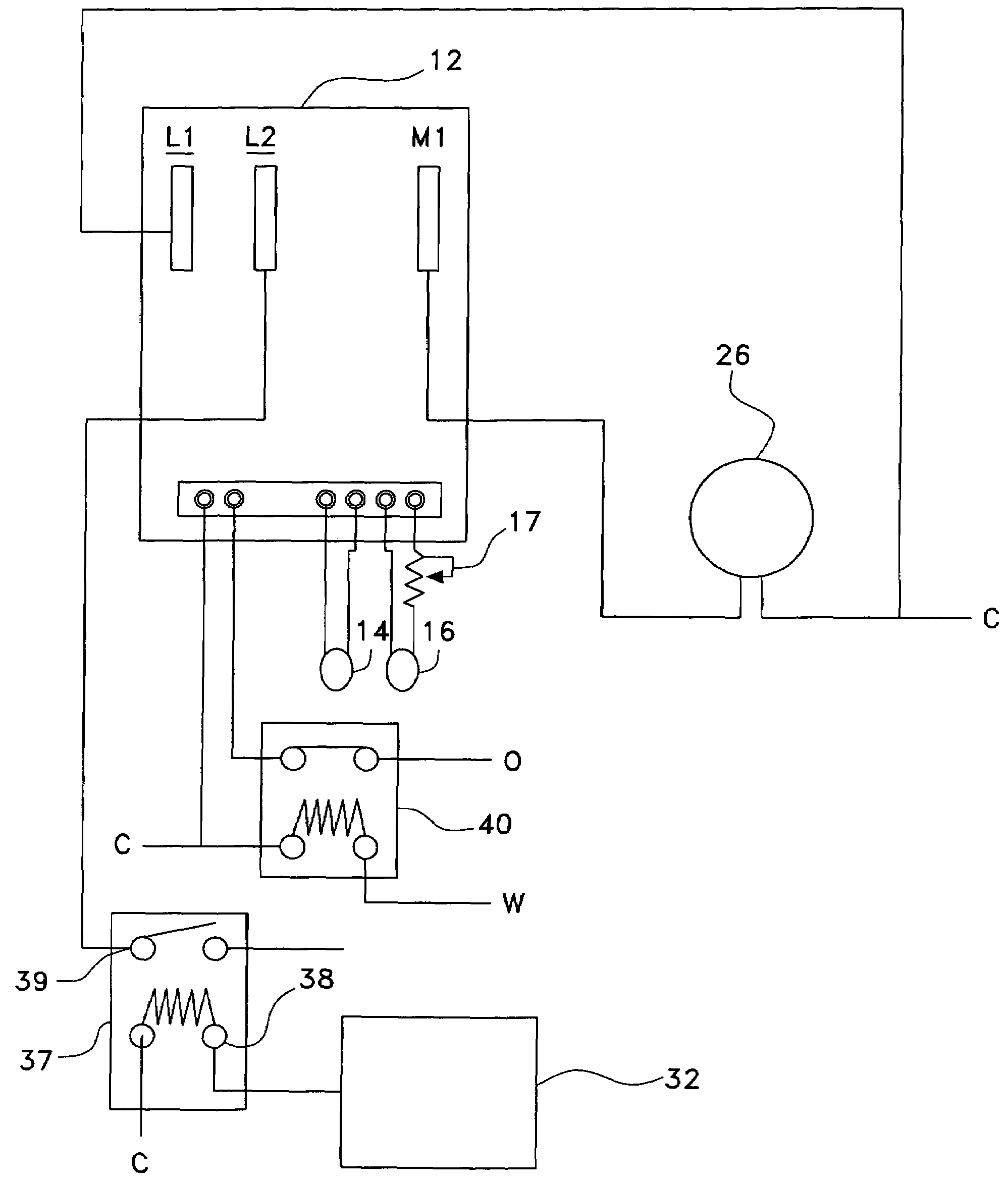
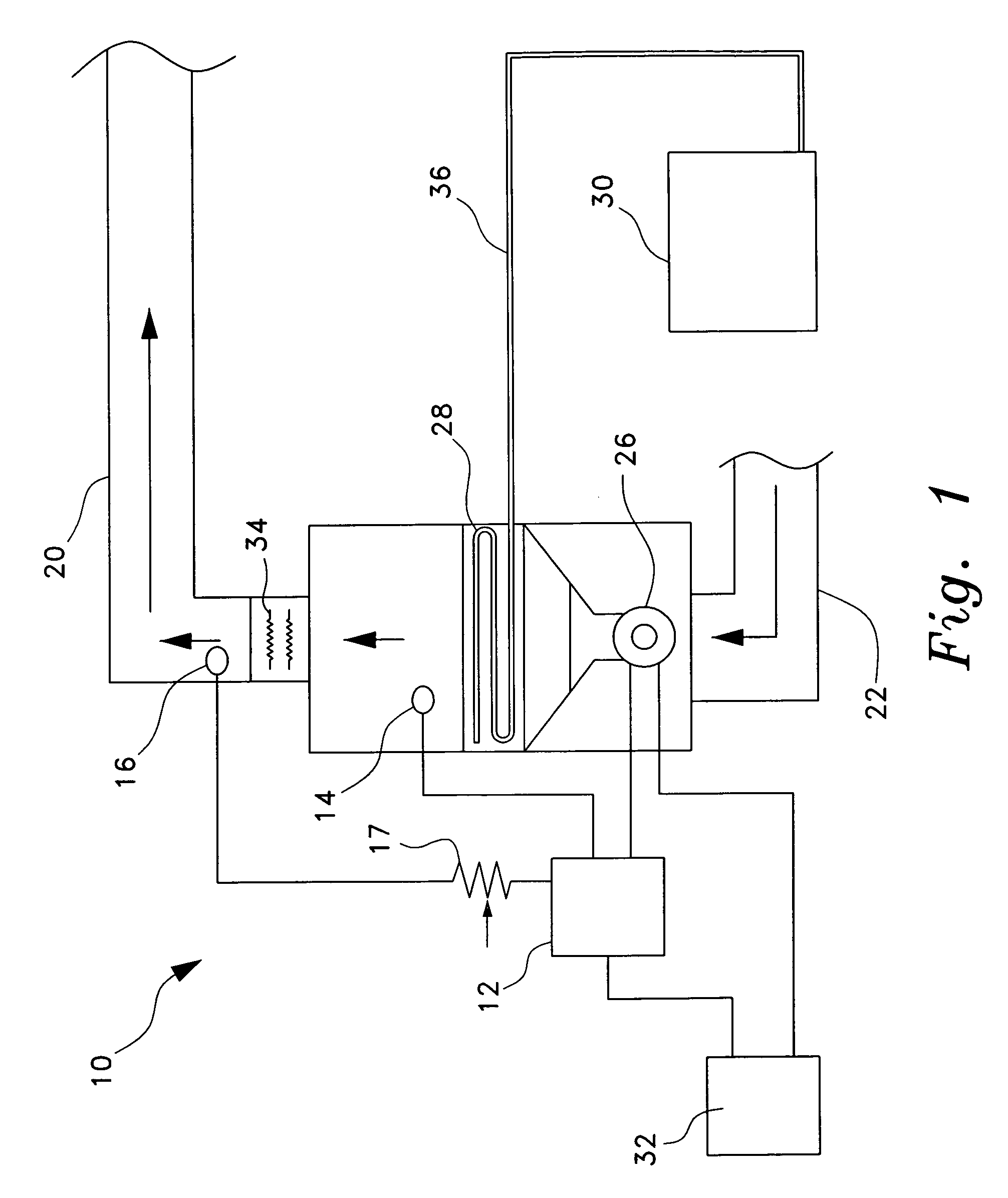
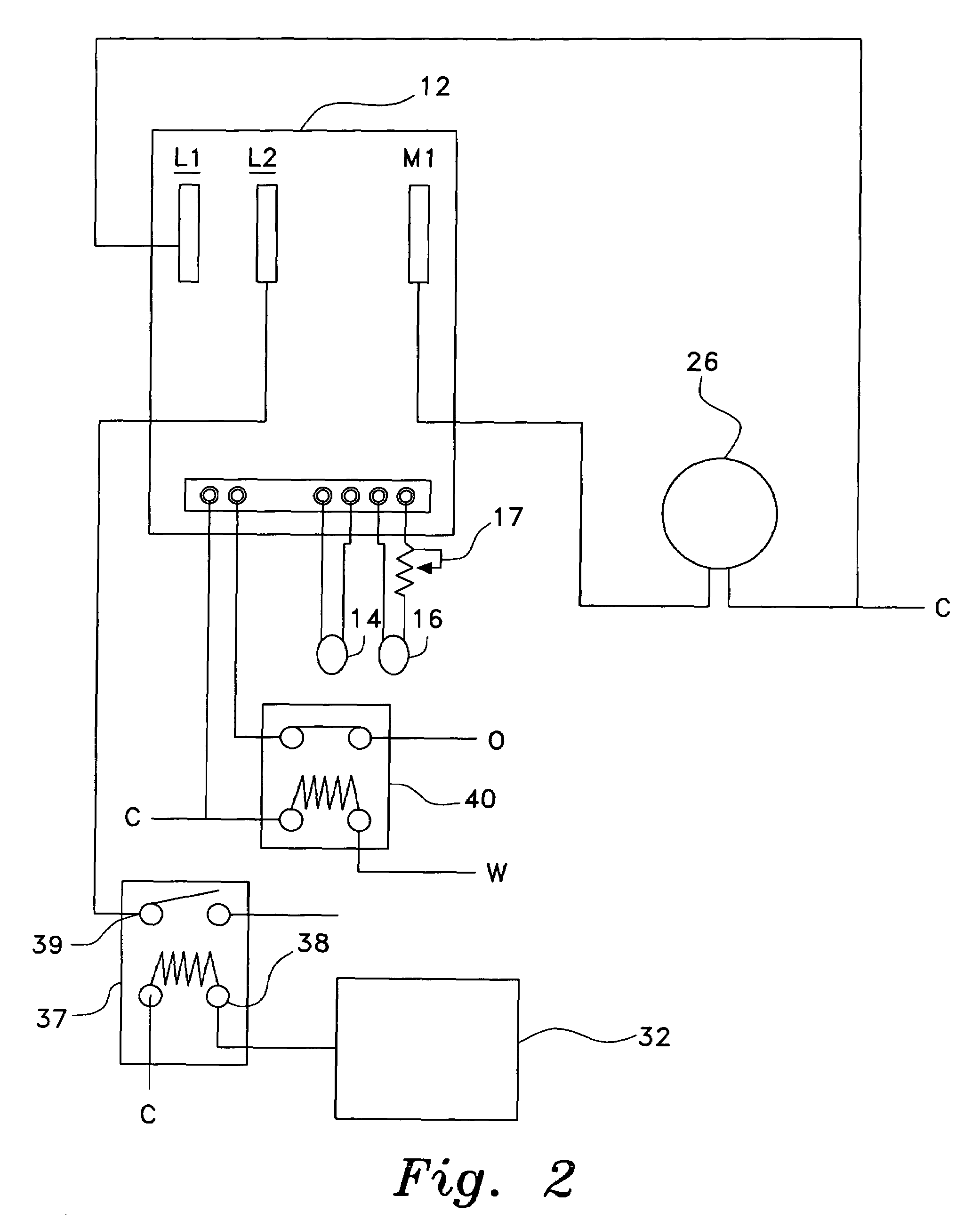
[0028]The present invention is a system and method for increasing efficiency in heat pump systems. Referring to FIGS. 1-3, a heat pump system 10 incorporating a system for increasing efficiency in heat pump systems according to the present invention is shown. The heat pump system 10 has, in a generally known configuration, an outdoor condenser unit 30 connected by refrigerant lines 36 to an indoor heat-exchanging coil 28. The indoor heat-exchanging coil 28 is disposed, along with a blower fan 24 and blower motor 26, within ductwork comprising a return duct 22 and a supply duct 20. Resistive heating elements 34 are disposed downstream of the indoor heat-exchanging coil 28. An indoor thermostat 32 controls the operation of the blower motor 26. Typically, the thermostat 32 operates a motor relay 37 to switch the fan motor 26. As shown in FIG. 2, the thermostat 32 is in communication with a switching input 38 of the motor relay 37. On receiving a signal from the thermostat 32, a switche...


PUM


Abstract

The system and method for increasing efficiency of heat pumps employs temperature sensors to measure the indoor refrigerant coil (indoor heat exchanger) and supply duct air temperature in a heat pump system to vary the indoor air flow rate based on the amount of heat being supplied by the heat pump. By monitoring the indoor refrigerant coil temperature, and the supply duct air temperature near the unit, the airflow can be adjusted to match the BTU (heat) output of the heat pump system. Less air flow over a cooler indoor refrigerant coil temperature allows increased, more efficient, heat transfer, allowing the cooler indoor refrigerant coil temperature to more effectively warm the air. Additionally, with airflow reduced when the indoor refrigerant coil is operating at lower than optimal temperatures or during a defrost cycle, the reduced airflow into living spaces presents a less drafty and more comfortable condition.

Description

CROSS-REFERENCE TO RELATED APPLICATION[0001]This application claims the benefit of U.S. Provisional Patent Application Ser. No. 60 / 575,844, filed Jun. 2, 2004.BACKGROUND OF THE INVENTION[0002]1. Field of the Invention[0003]The present invention relates to heating systems. More specifically, the invention is a system and method for increasing heating efficiency in heat pumps.[0004]2. Description of the Related Art[0005]Heat pump systems for residential and commercial heating and air conditioning applications are well known among heating, ventilating, and air conditioning (HVAC) systems, and are popular for their relative energy efficiency in a broad range of heating operations.[0006]A heat pump system typically uses an outdoor heat-exchanging coil to extract heat from outdoor air. Refrigerant flowing through the coil is heated, and pumped through an indoor heat-exchanging coil. An air-circulating blower moves indoor air through ductwork and over the indoor heat-exchanging coil, warmi...

Claims


Application Information

Patent Timeline
Patent Type & Authority Patents(United States)
IPC IPC(8): F25D17/04F24F11/00G05D23/00F25B49/00F25B13/00F25B30/02F25D17/00
CPCF25B30/02F25B2313/0293F25B2313/0314Y10S236/09
Inventor THOMPSON, THOMAS W.
Owner THOMPSON THOMAS W
Why Eureka
Try Eureka