Biomolecule microarray support

a biomolecule and microarray technology, applied in the field of biomolecule microarray support, can solve the problems of reducing the usable chamber area, dividers affecting spot deposition and scanning, and causing leakage between chambers

Inactive Publication Date: 2008-03-18
CAMACHO JOSEPH +1
View PDF3 Cites 28 Cited by
  • Summary
  • Abstract
  • Description
  • Claims
  • Application Information

AI Technical Summary

Problems solved by technology

Such fixed dividers interfere with spot deposition and scanning.
However, the thick side walls reduce the usable chamber ar

Method used


Image

  • Biomolecule microarray support
  • Biomolecule microarray support
  • Biomolecule microarray support

Examples


Embodiment Construction

FIG. 1

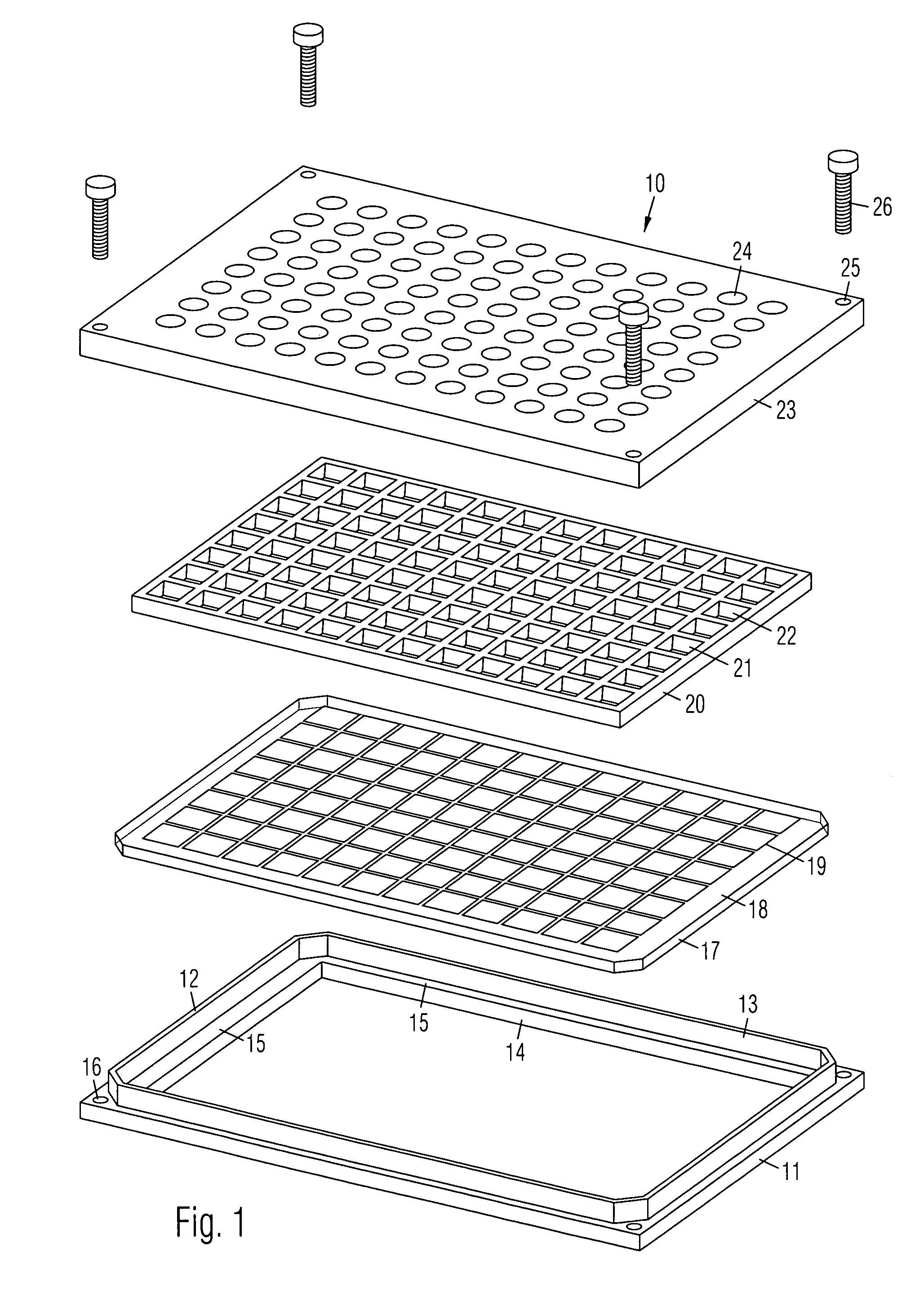
[0016]A preferred embodiment of a biomolecule microarray support 10 is shown in an exploded view in FIG. 1. It is comprised of a frame 11 with upward projecting side walls 12 and 13 surrounding an opening 14. Side walls 12 and 13 may be connected as shown or they may be discontinuous. There is a shoulder 15 around opening 14. First fastener holes 16 are positioned at respective corners of frame 11.

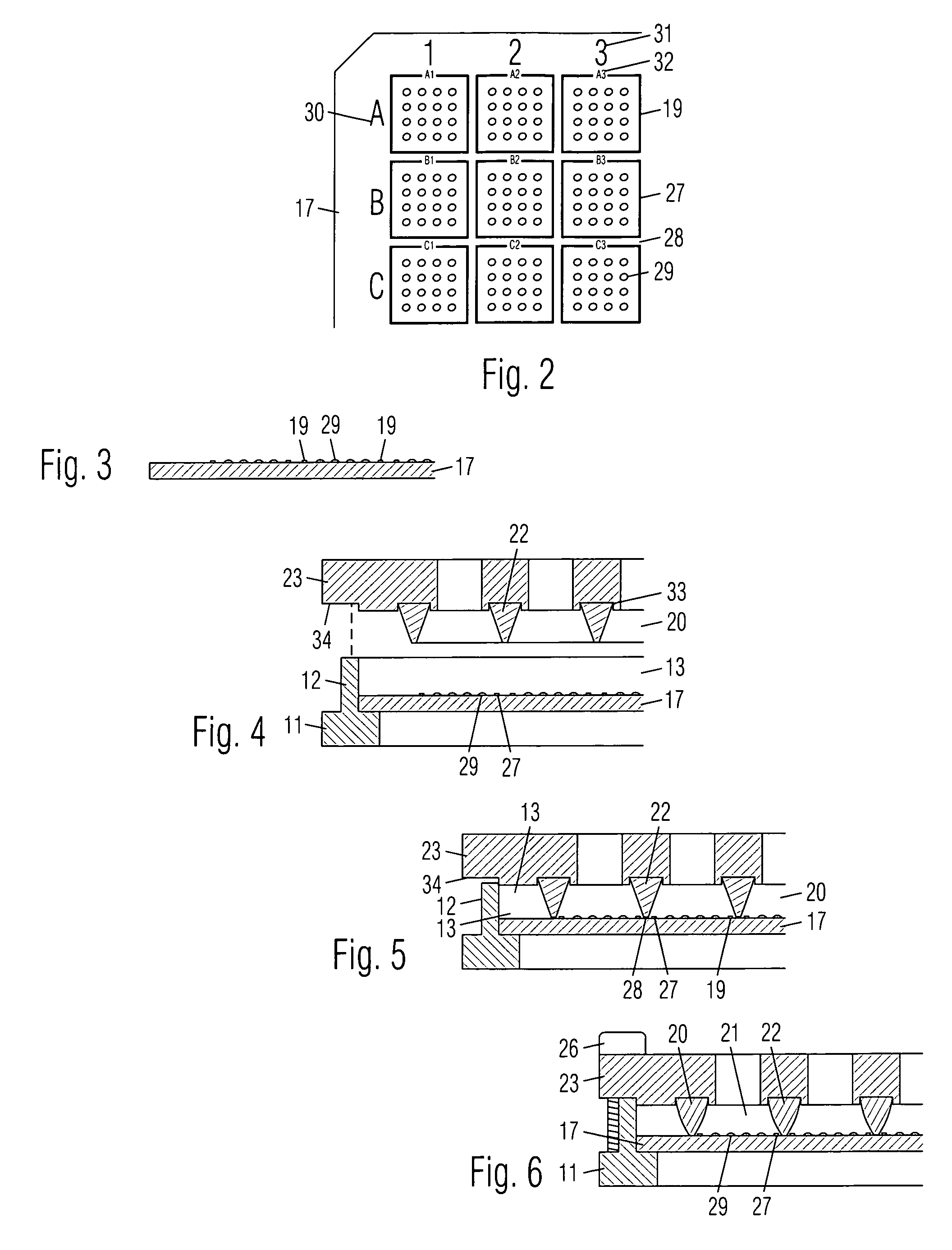
[0017]A transparent plate or substrate 17 is for detachably positioning on frame 11 within side walls 12 and 13 in alignment with opening 14 and supported by shoulder 15. There is an organic coating 18 on top of substrate 17 to help bind biomolecules. A printed hydrophobic grid 19 is arranged on substrate 17 for separating spots of biomolecule samples. A resilient grid-shaped gasket 20 with an array of chambers 21 is for positioning on substrate 17 in alignment with grid 19. Chambers 21 are defined by intersecting dividing walls 22.

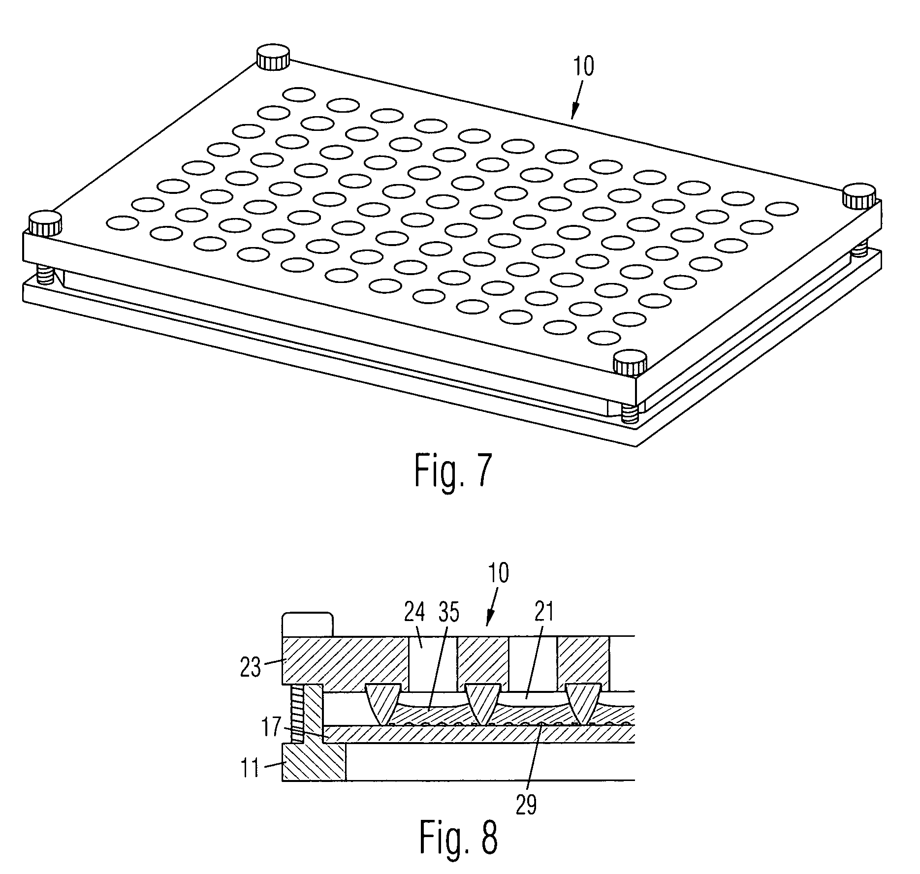
[0018]A clamping plate 23 is for positioning on gask...


PUM


Abstract

A biomolecule microarray support is comprised of a frame with upward projecting side walls. A transparent substrate is detachably positioned on the frame within the walls. A printed hydrophobic grid is arranged on the substrate for receiving spots of biomolecule samples. Each square on the grid is identified with a position number. A resilient gasket with an array of chambers is position on the substrate in alignment with the grid. The chambers are defined by dividing walls which are tapered from top to bottom. A clamping plate is positioned on the gasket which is received in stabilizing grooves under the clamping plate. Holes on the clamping plate aligned with the chambers allow a hybridization fluid to be introduced into the chambers. Fasteners connect the clamping plate and the frame to tightly compress the gasket against the substrate to seal the chambers from each other.

Description

BACKGROUND OF THE INVENTION[0001]1. Field of the Invention[0002]The invention broadly relates to devices for supporting biomolecule samples for laboratory analysis.[0003]2. Prior Art[0004]Analysis of biomolecule samples is typically performed by depositing small spots of different molecules in a microarray on a supporting device. The spots are dried, and a solution containing an unknown with chemical tags is applied to the dried droplets. Binding reactions or hybridization occur where the unknown binds to the spots. The tags in the complementary compounds in the solution are detected by optical or radiosensitive scanning.[0005]A typical supporting device is comprised of a glass plate and a divider thereon which defines an array of chambers for receiving the spots and solution. Some prior art devices have dividers permanently attached to the glass plates with adhesive. Such fixed dividers interfere with spot deposition and scanning. Further, the adhesive requires a relatively wide co...

Claims


Application Information

Patent Timeline
IPC IPC(8): C12M3/00
CPCB01L3/5085B01L3/5088B01L2200/0689B01L2300/0636B01L2300/0829
Inventor CAMACHO, JOSEPHRICHARDSON, GREG
Owner CAMACHO JOSEPH
Why Eureka
Try Eureka