Apparatus for analyzing and sorting biological particles

a flow cytometer and biological particle technology, applied in the field of separation of particles, can solve the problems of large amount of valuable laboratory and clinic space occupied by flow cytometers, time-consuming and costly methods, and inconvenient use,

Inactive Publication Date: 2008-03-18
CYTOPEIA
View PDF12 Cites 9 Cited by
  • Summary
  • Abstract
  • Description
  • Claims
  • Application Information

AI Technical Summary

Benefits of technology

[0007]The invention provides an apparatus including (a) a frame having a boundary plane; (b) a flow chamber supported by the frame, the flow chamber placed a distance from the boundary plane; (c) a radiation source, the radiation source directed away from the flow chamber and away from the exterior side of the boundary plane, and (d) a first reflective surface placed to direct a radiation beam in a path crossing the boundary plane to the flow chamber; (e) one or more reflective surfaces placed to direct a radiation beam from the radiation source to the first reflective surface, the path from the radiation source to the flow chamber being at least 1.5 times the distance from the flow chamber to the boundary plane.

Problems solved by technology

However, impurities that co-fracionate with a biological particle of interest in a flow sorting method can produce false results in a diagnostic assay or can have adverse consequences in a therapeutic procedure.
Thus, flow sorting methods often require decontamination procedures to remove unwanted residual materials between sample applications.
Such methods can be time consuming and costly and are often incomplete.
Currently, flow cytometers are bulky instruments that occupy large amounts of valuable laboratory and clinic space.
Reduction in flow cytometer size has previously come at the expense of functionality or performance.
A disadvantage of this approach is that interchanging components can be time consuming, thereby reducing the throughput of the instrument or precluding the full range of analyses available for a single sample.

Method used


Image

  • Apparatus for analyzing and sorting biological particles
  • Apparatus for analyzing and sorting biological particles
  • Apparatus for analyzing and sorting biological particles

Examples


Embodiment Construction

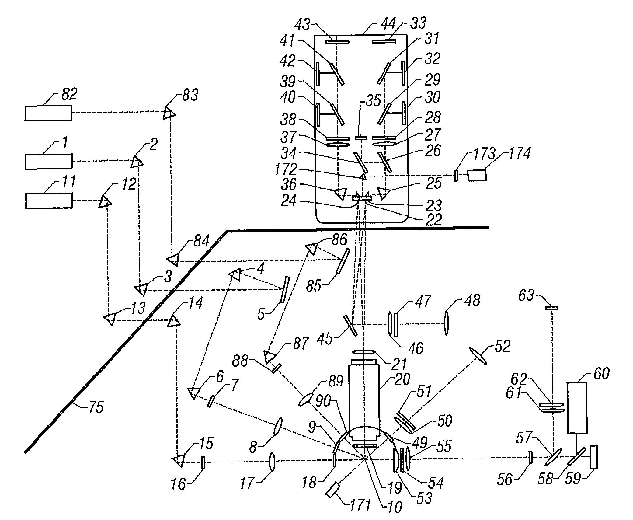
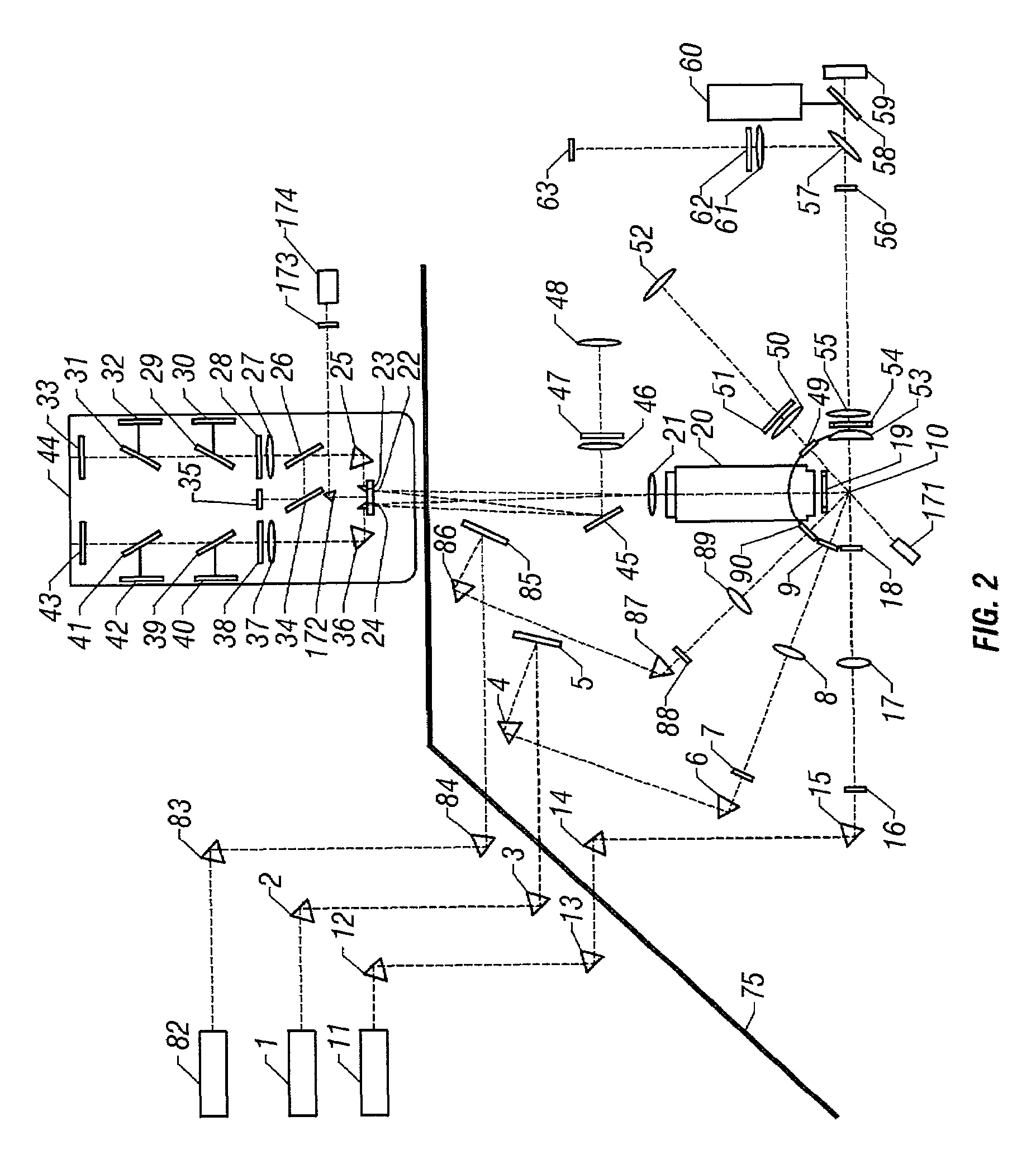
[0014]This invention provides an apparatus for separating and sorting particles in a mixture. In one embodiment, an apparatus of the invention can be a flow cytometer for analyzing or sorting biological particles such as cells, organelles or macromolecules. An apparatus of the invention can include a rigid frame to which optical devices and flow system devices can be attached. Optical devices can be placed on the rigid frame of the instrument such that excitation radiation beam paths propagated from one or more radiation sources are folded within a compact volume prior to contacting a sample stream directed through a flow system to a flow chamber. Optical components can also be placed to direct two or more separate radiation beams from substantially parallel radiation sources to a flow chamber by directing the two or more radiation beams across the same boundary plane of a frame supporting the flow chamber. Parallel placement of two or more radiation sources provides the advantage o...


PUM

PropertyMeasurementUnit
diameteraaaaaaaaaa
pressureaaaaaaaaaa
diameteraaaaaaaaaa

Abstract

The invention provides an apparatus including (a) a frame having a boundary plane; (b) a flow chamber supported by the frame, the flow chamber placed a distance from the boundary plane; (c) a radiation source, the radiation source directed away from the flow chamber and away from the exterior side of the boundary plane, and (d) a first reflective surface placed to direct a radiation beam in a path crossing the boundary plane to the flow chamber; (e) one or more reflective surfaces placed to direct a radiation beam from the radiation source to the first reflective surface, the path from the radiation source to the flow chamber being at least 1.5 times the distance from the flow chamber to the boundary plane.

Description

BACKGROUND OF THE INVENTION[0001]This invention relates generally to separation of particles from mixtures and, more specifically, to flow cytometers for analyzing and sorting biological particles.[0002]Flow cytometry is a valuable method for the analysis and isolation of biological particles such as cells and constituent molecules. As such it has a wide range of diagnostic and therapeutic applications. The method utilizes a fluid stream to linearly segregate particles such that they can pass, single file, through a detection apparatus. Individual cells can be distinguished according to their location in the fluid stream and the presence of detectable markers. Thus, a flow cytometer can be used to produce a diagnostic profile of a population of biological particles. For example, flow cytometry has been used to measure the decline or maintenance of immune cells during the course of treatment for HIV infection and to determine the presence or absence of tumor cells for prognosis and d...

Claims


Application Information

Patent Timeline
Patent Type & Authority Patents(United States)
IPC IPC(8): G01J3/30G01N15/14
CPCG01N15/1434G01N2015/149
Inventor VAN DEN ENGH, GER
Owner CYTOPEIA
Why Eureka
Try Eureka