On-vehicle antenna system and electronic apparatus having the same

a technology of electronic equipment and antenna system, which is applied in the direction of antennas, non-resonant long antennas, antennas in movable bodies, etc., can solve problems such as difficult to solve deterioration problems, and achieve the effects of improving reception characteristics, superior reception characteristics, and improving reception characteristics

Inactive Publication Date: 2010-06-22
PANASONIC CORP
View PDF35 Cites 9 Cited by
  • Summary
  • Abstract
  • Description
  • Claims
  • Application Information

AI Technical Summary

Benefits of technology

[0023]The present invention aims, on the basis of new knowledge, to overcome the inconvenience and offers an on-vehicle antenna system which would provide superior reception characteristics.
[0024]An on-vehicle antenna system in accordance with the present invention is installed at glass portion of a vehicle, with direction of the greatest radiation pattern directed towards ahead of the vehicle while the smallest radiation pattern towards behind of the vehicle. Or, it is installed at glass portion of a vehicle, with direction of the greatest radiation pattern directed towards outside of the vehicle's cabin in relation to the glass surface while the smallest radiation pattern towards inside of the cabin in relation to the glass surface. Being different from the conventional on-vehicle antenna systems which have non-directional radiation pattern, an on-vehicle antenna system in the present invention employs a certain directional antenna. The antenna system can receive only those waves arriving from outside of the vehicle, with those reflected / scattered waves suppressed. Receiving of the reflected / delayed waves, which being a key deteriorating factor with the antenna reception characteristics, is thus suppressed, and the reception characteristics are improved.

Problems solved by technology

Based on the new understandings, the engineers conceived that it was difficult to solve the deterioration issue through the conventional technical philosophy of pursuing an antenna of non-directional characteristics, or using a conventional monopole antenna aiming to reduce the overall size.

Method used


Image

  • On-vehicle antenna system and electronic apparatus having the same
  • On-vehicle antenna system and electronic apparatus having the same
  • On-vehicle antenna system and electronic apparatus having the same

Examples


first exemplary embodiment

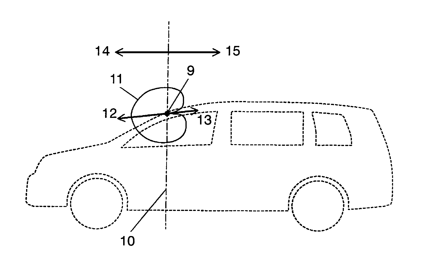
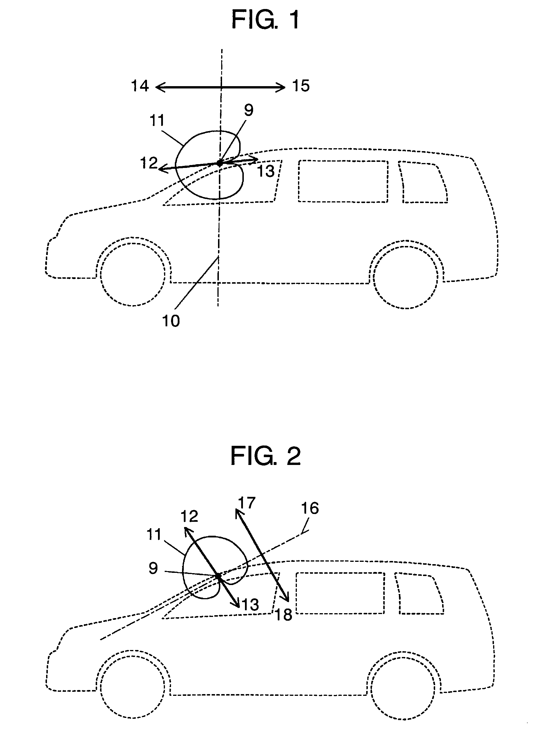
[0080]An on-vehicle antenna system in accordance with a first embodiment of the present invention is described with reference to FIG. 1. In the following descriptions, the terminology “radiation pattern” means a radiation pattern of an on-vehicle antenna system itself, not a radiation pattern of that which is installed at glass portion of a vehicle and generated as the result of electromagnetic coupling with a metal frame of the vehicle. Namely, it does not mean a radiation pattern which contains an influence of metal frame.

[0081]“Direction of the greatest radiation pattern” means, in an exemplary illustration FIG. 1, direction of the greatest gain 12 of radiation pattern 11 of the antenna system, as viewed from the location of power supply portion 9. “Direction of the smallest radiation pattern” means, in an exemplary illustration FIG. 1, direction of the smallest gain 13 of radiation pattern 11 of the antenna system, as viewed from the location of power supply portion 9.

[0082]“Dir...

second exemplary embodiment

[0112]An on-vehicle antenna system in accordance with a second embodiment of the present invention is described referring to FIG. 10 and FIG. 11.

[0113]FIG. 10 shows a vehicle viewed from above; dipole antenna 27 is installed at upper area of front windshield glass 3 away from roof board 1 by an antenna installation distance S. When dipole antenna 27 is disposed at the upper area of front windshield glass 3 as illustrated in FIG. 10, it makes an electromagnetic coupling with roof board 1 and the intrinsically non-directional radiation pattern changes to a certain directional radiation pattern. The radiation pattern (directional gain) is shown in FIG. 11. In FIG. 11, the directional gain (Y Z plane, horizontally polarized wave) of dipole antenna 27 disposed as illustrated in FIG. 10 is shown. The directional gain changes depending on the antenna installation distance S.

[0114]Taking notice on a direction of wave angle 0 degree-30 degrees, or the angle of high signal arriving probabilit...

third exemplary embodiment

[0123]FIG. 12 shows an on-vehicle antenna system in accordance with a third exemplary embodiment of the present invention, as viewed from above. In FIG. 12, monopole antenna 28 and monopole-structured Yagi antenna 29 are disposed at the upper area of front windshield glass 3 with an antenna installation distance S from roof board 1. Monopole antenna 28 and monopole-structured Yagi antenna 29 are disposed approximately perpendicular to pillar 30. In this setup, roof board 1 works as the reflector of monopole-structured Yagi antenna 29, which contributes to reduce the size of antenna system. When monopole antenna 28 is disposed at the upper area of front windshield glass 3 as shown in FIG. 12, it is electromagnetically coupled with roof board 1, and the radiation pattern, which intrinsically has a substantially non-directional pattern, changes into a certain directional pattern. FIG. 13 shows radiation pattern of monopole antenna 28 with X Y horizontally polarized wave. As understood ...


PUM


Abstract

An on-vehicle antenna system which offers a superior receiving performance, by suppressing reception of reflected / scattered waves coming from inside of the vehicle's cabin; these reflected / scattered waves being an adverse factor which deteriorates signal receiving performance of an antenna. The antenna system is installed at glass pane portion of a vehicle with direction (12) of the greatest radiation pattern (11) directed towards ahead (14) of the vehicle from boundary plane (10) containing power supply portion (9), while direction (13) of the smallest radiation pattern (11) towards behind (15) of the vehicle. The above-configured antenna system can suppress those waves reflected / scattered in the vehicle cabin from being received; as the result, it demonstrates improved characteristics.

Description

TECHNICAL FIELD[0001]The present invention relates to an on-vehicle antenna system for installation in vehicles, electronic apparatus such as radio receivers, television receivers, portable telephone systems, VICS (Vehicle Information and Communication System), etc. The invention relates also to an electronic apparatus mounted with the antenna system.BACKGROUND ART[0002]There are various types of antenna systems mounted on a vehicle nowadays. For example, radio receivers, television receivers, portable telephone systems, GPS (Global Positioning System), ETC (Electronic Toll Collection System), VICS, etc. have their own antenna systems that fit to their specific operation. Since vehicles are mobile substance, it is not easy for them to recognize direction of a certain signal where it is coming from, with these exceptions of GPS, ETC, etc. where recognition of the signal direction is comparatively easy. Based on the general understanding, radiation pattern of antenna for vehicles othe...

Claims


Application Information

Patent Timeline
Patent Type & Authority Patents(United States)
IPC IPC(8): H01Q1/32
CPCH01Q19/30H01Q1/1271
Inventor FUKUSHIMA, SUSUMUHOSHIAI, AKIHIRO
Owner PANASONIC CORP
Why Eureka
Try Eureka