Jigsaw

a technology of jigsaw and cam, which is applied in the field of jigsaw, can solve the problems of large vibration of the main body, difficult cam formation, high price of jigsaw, etc., and achieve the effects of reducing the vibration to be generated in the main body, easy discharge, and waste of friction

Active Publication Date: 2008-04-01
KOKI HLDG CO LTD
View PDF13 Cites 22 Cited by
  • Summary
  • Abstract
  • Description
  • Claims
  • Application Information

AI Technical Summary

Benefits of technology

[0011]According to an aspect of the invention, a jigsaw can work with little vibration and excellent cutting performance.
[0014]According to the above aspects, the saw blade can swing to follow such an excursion that a cutting speed is improved by the cam which can be easily formed. Accordingly, the inexpensive jigsaw having high cutting performance can be provided.
[0015]According to the above-aspects, the outer surface of the cam can be smoothly formed so that an oscillation due to the jigsaw can be decreased.
[0019]Therefore, even when an operator carries out an operation while he / she strongly pushes the main body forward, the saw blade is already separated from a surface to be cut at a point of time when it reaches the uppermost point, and the vibration to be generated in the main body will be diminished. Further, chips are easily discharged, wasteful friction between the saw blade and a surface to be cut disappears, and cutting performance improves further.
[0020]Accordingly, it is possible to provide a jigsaw with little vibration and excellent cutting performance.

Problems solved by technology

In addition, according to JP-A-53-117867, the jigsaw is expensive since it is difficult to form the cam.
A formation of the cam is difficult, so that the saw blade does not smoothly change to follow an excursion thereof.
This instantaneous change in the direction of force causes large vibration of the main body.
Further, since prompt descent of the saw blade is hindered, the cutting speed may be lowered.

Method used


Image

  • Jigsaw
  • Jigsaw
  • Jigsaw

Examples


Embodiment Construction

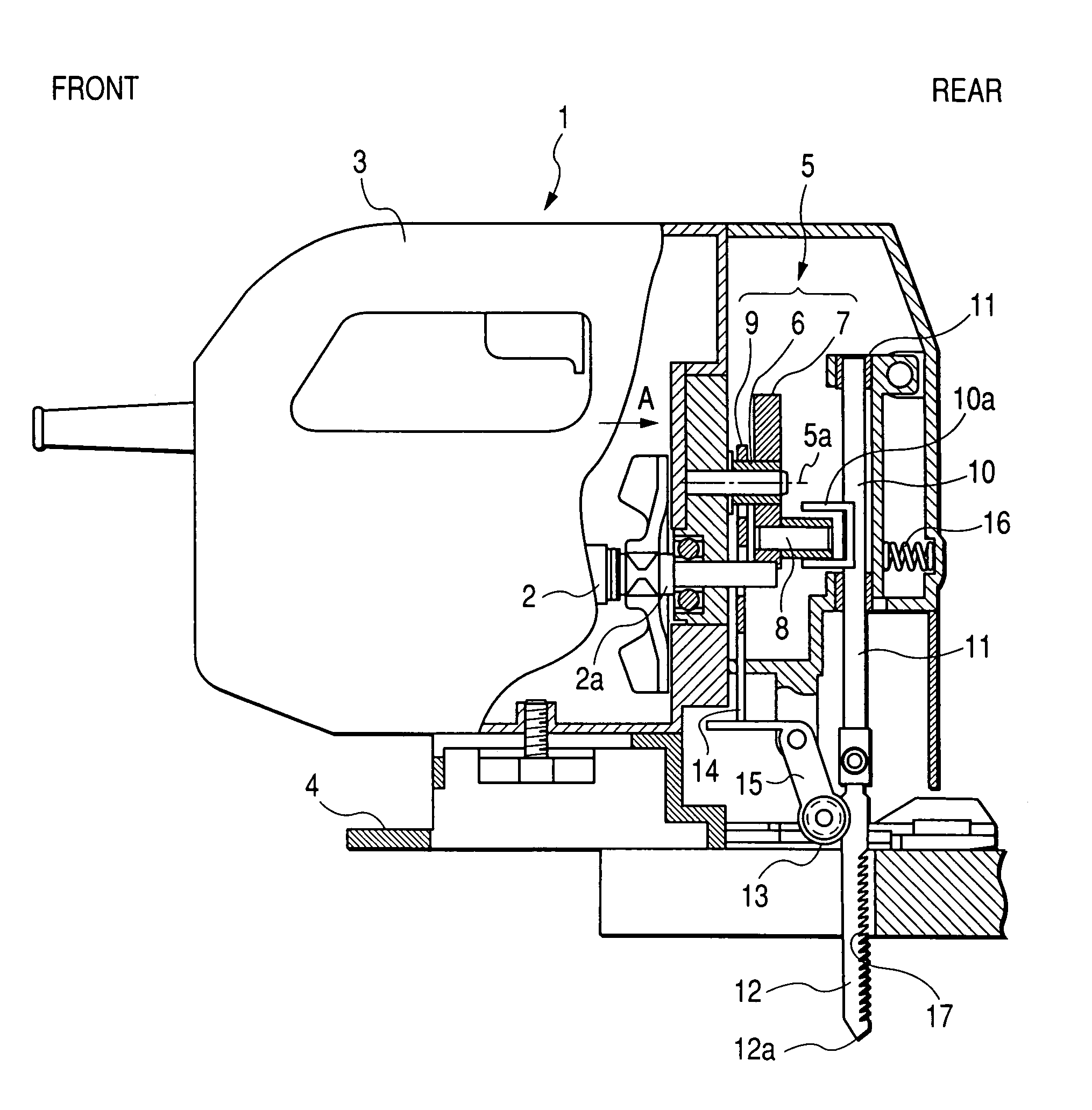
[0030]A jigsaw according to an embodiment of the invention will be described referring to FIGS. 1 to 8. In the description, the right side of FIG. 1 is defined as the front side of the jigsaw 1, the left side of FIG. 1 is defined as the rear side of the jigsaw 1, the upper side of FIG. 1 is defined as the upper side of the jigsaw 1, and the lower side of FIG. 1 is defined as the lower side of the jigsaw 1.

[0031]As shown in FIG. 1, the jigsaw 1 includes a motor 2 having a rotary shaft 2a that extends in the front-and-rear direction, a housing 3 as an external frame that accommodates the motor 2, and a base 4 provided below the housing 3.

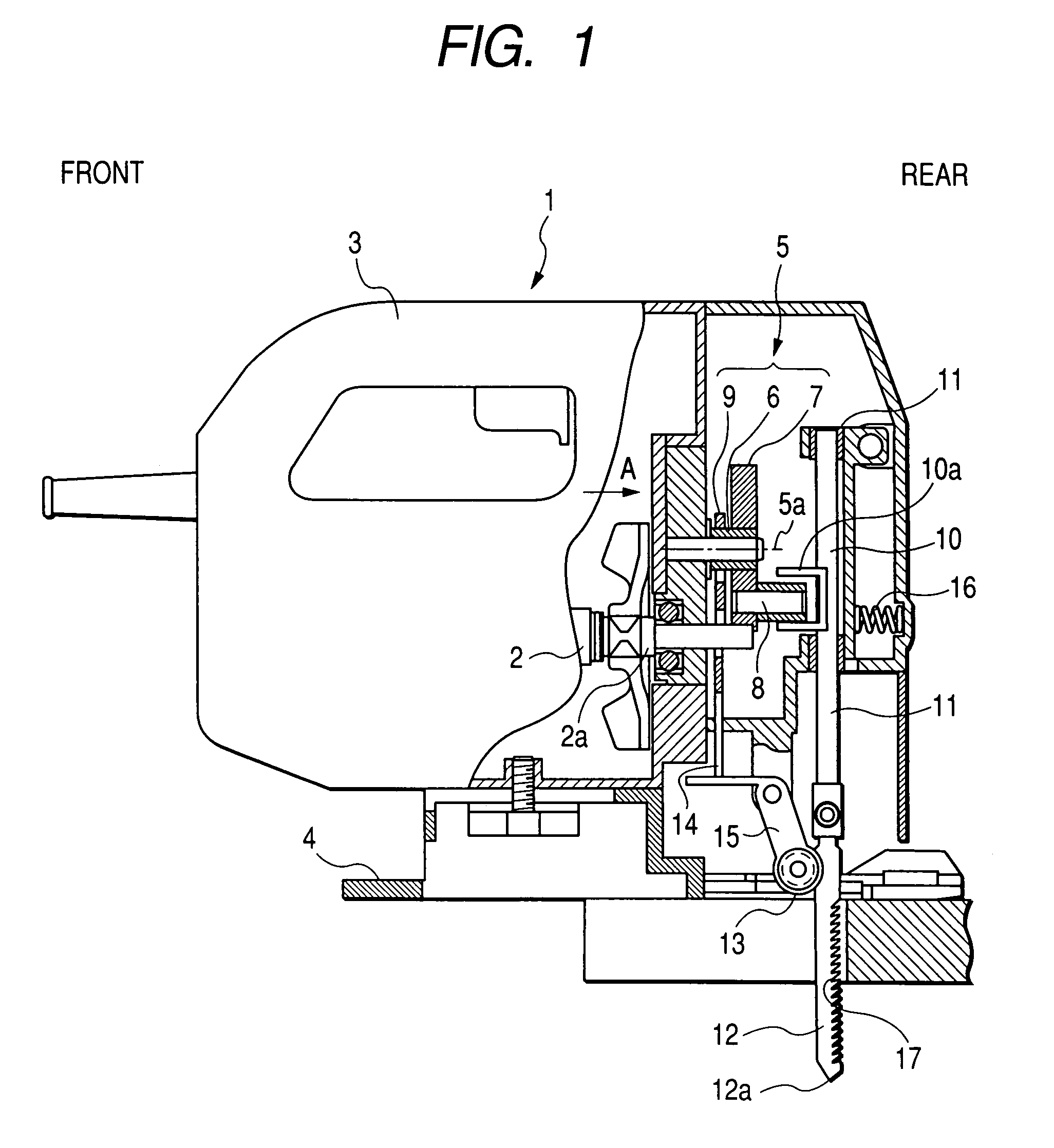
[0032]A rotating section 5 that meshes with a pinion formed at a tip of the rotary shaft 2a so as to be driven rotationally is provided within the housing 3. The rotating section 5 includes a spindle 6 that is a rotary shaft, a gear 7 provided on the spindle 6, a pin 8 provided in an eccentric position of the gear 7, and a cam 9 provided on the spindl...


PUM

PropertyMeasurementUnit
phase θaaaaaaaaaa
phase θaaaaaaaaaa
thicknessaaaaaaaaaa

Abstract

An outer peripheral surface of a cam has an apex disposed of distance from a rotational axis, a first region adjacent the apex opposite to the direction of rotation that increases in distance from the rotational axis during rotation, and a second region adjacent the apex in the rotational direction that decreases in distance from the rotational axis of the cam with the rotation thereof. The apex is disposed where the phase θ thereof advances by 15 degrees and 55 degrees or less in the rotational direction from a position symmetrical to the rotational axis. The rate of change between the second region and the rotational axis is greater than the rate of change between the first region and the rotational axis. A retreat amount X when a saw blade reaches an uppermost point c from a foremost point is set to 0.8 mm.

Description

CROSS-REFERENCE TO RELATED APPLICATIONS[0001]This application is based on and claims the benefit of priority from the prior Japanese Patent Application No. 2005-248509, filed on Aug. 29, 2005.BACKGROUND[0002]1. Technical Field[0003]The present invention relates to a jigsaw in which a saw blade is caused to reciprocate in an up-and-down direction by a motor and a workpiece, such as timber, is cut while a main body is forcedly pushed forward, and more specifically, to a mechanism that reciprocates a saw blade even in the front-and-rear direction.[0004]2. Description of Related Art[0005]A jigsaw in which a saw blade is caused to reciprocate in an up-and-down direction by a motor and a workpiece, such as timber, is cut while a main body is forcedly pushed forward, is much used for cutting boards in housing construction using a 2×4 construction method. It is known that this jigsaw is advantageously adapted to reciprocate a saw blade not only in an up-and-down direction but also in a fron...

Claims


Application Information

Patent Timeline
Patent Type & Authority Patents(United States)
IPC IPC(8): B27B19/09
CPCB23D49/165Y10T74/18256
Inventor IMAI, TERUOKUMASAKA, TAIICHIWATANABE, HIDEKIOTSU, SHINKIKOMAZAKI, YOSHIICHI
Owner KOKI HLDG CO LTD
Why Eureka
Try Eureka