Pneumatic tire and tire wheel assembly
A technology of pneumatic tires and tires, applied in pneumatic tires, tire parts, tire treads/tread patterns, etc., can solve problems such as no consideration of tire skid resistance, inability to reduce noise and tire skid resistance, uneven wear, etc. , to achieve the effect of improving control stability, enhancing stiffness, and inhibiting shrinkage
- Summary
- Abstract
- Description
- Claims
- Application Information
AI Technical Summary
Problems solved by technology
Method used
Image
Examples
example 1
[0189] Each of the example tires and comparative example tires each having a tire size of 225 / 55R16 was assembled on a 7.0J-16 rim, charged with an air pressure of 210 kPa, and then mounted on a vehicle. Under the condition that the negative camber of the front wheels is 0.3° and the negative camber of the rear wheels is 0.5°, the vehicle is actually driven with two passengers, and the tire tires on a dry road surface are measured during the process. The wear rate of the surface sections between the shoulders, the speed at which tire skidding occurs, the vehicle interior noise and handling stability.
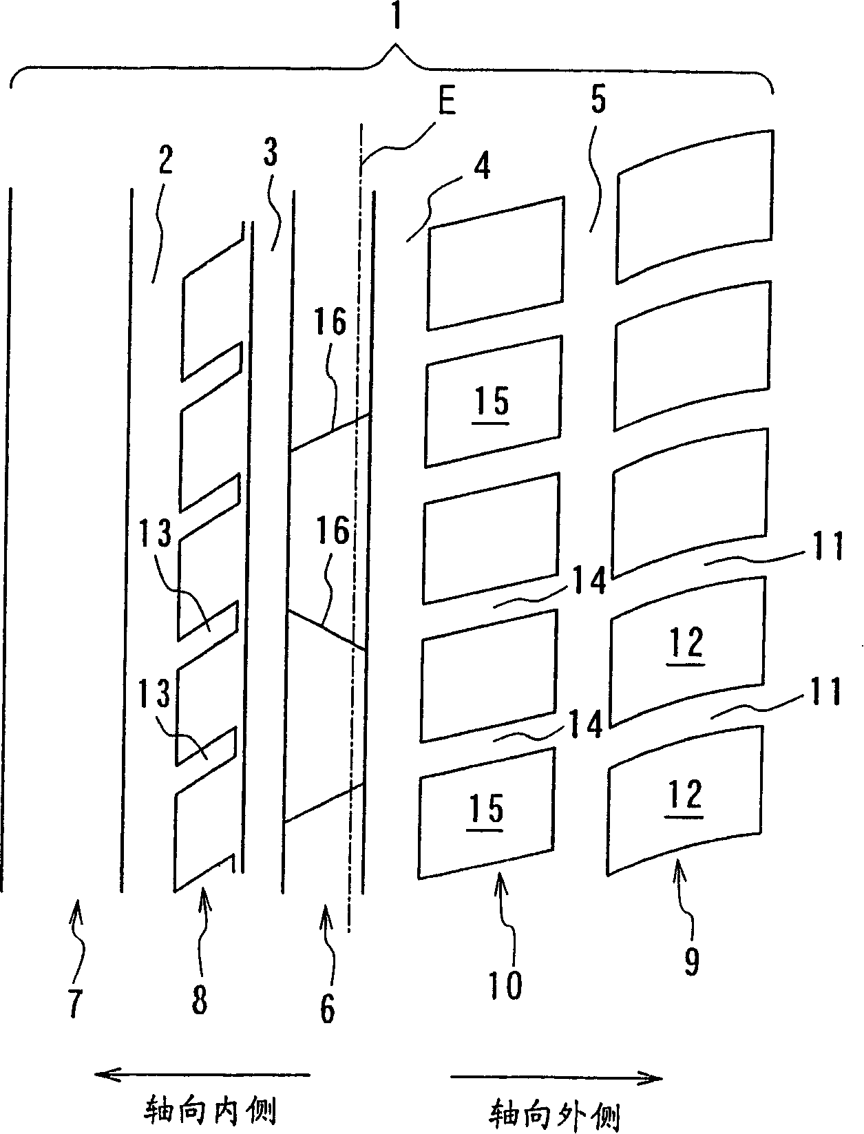
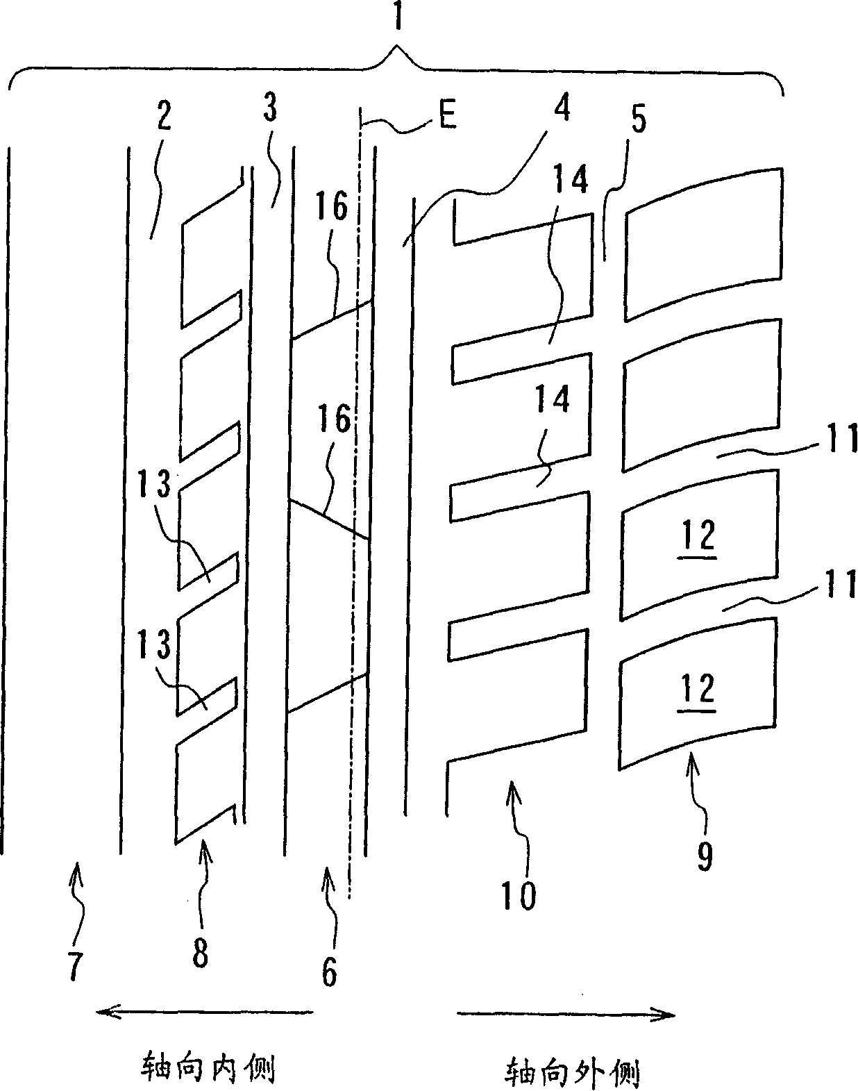
[0190] Example tire 1 has figure 1 Tread pattern shown in which the oblique grooves in the second inner land portion row have an angle of 45° with respect to the transverse direction of the tread, and the lug grooves in the second outer land portion row have an angle of extension is 30°, and the average extension angle of the lug grooves in the row of axially outer shoulder lan...
example 2
[0214] The tire size is 215 / 45R17 and the tread pattern is as follows Figure 25 Each of the example tires shown and the comparative example tires were assembled on a rim of 7.5J×17 and filled with an internal pressure of 220kPa, a camber angle of -0.5° was applied to make the contact length on the axial inner side long, and then at 30km Change the slip angle from 0 to 5 degrees at a speed of 1 / h to measure the resulting turning direction stress.
[0215] When the difference in stress in the direction of turn between 0° and 1° is Cf1, the difference in stress in the direction of turn between 0° and 2.5° is Cf2, and the difference in stress in the direction of turn between 0° and 5° With a value of Cf3, if Cf2 / Cf1 is 2.5 and Cf3 / Cf1 is 5, turning direction stresses are generated linearly, while if Cf2 / Cf1 is greater than 2.5, turning direction stresses increase nonlinearly at locations with large slip angles , if Cf2 / Cf1 is less than 3, the stress in the turning direction decr...
Embodiment 3
[0224] Each of the example tires and comparative example tires each having a tire size of 235 / 45R17 was assembled on a rim of 8J×17, charged with an internal pressure of 210 kPa, and then mounted on a vehicle in which two passengers In the state, the camber angle at the front wheel is -0.4°, and that at the rear wheel is -0.6°.
[0225] • Carry out a wear test on the vehicle. The test condition is to drive 20,000km on expressways, ordinary roads and mountain roads according to the ratios of 50%, 40% and 10% respectively. After running, the wear amount ratios of the lateral central portions of the two shoulder portion rows on the two front wheels were measured. A case where the ratio is greater than 100 indicates that the axially inner side is extremely worn, and a case where the ratio is less than 100 indicates that the axially outer side is extremely worn.
[0226] • The vehicle was subjected to an acceleration test from a speed of 50 km / h in a water tank having a water dep...
PUM
 Abstract
Description
Claims
Application Information
 - R&D
- Intellectual Property
- Life Sciences
- Materials
- Tech Scout
- Unparalleled Data Quality
- Higher Quality Content
- 60% Fewer Hallucinations
Browse by: Latest US Patents, China's latest patents, Technical Efficacy Thesaurus, Application Domain, Technology Topic, Popular Technical Reports.
© 2025 PatSnap. All rights reserved.Legal|Privacy policy|Modern Slavery Act Transparency Statement|Sitemap|About US| Contact US: help@patsnap.com


