Eureka AIR delivers breakthrough ideas for toughest innovation challenges, trusted by R&D personnel around the world.

Reaction control system for obtaining preferable steering feeling

a technology of reaction control and steering feeling, applied in the direction of steering initiation, instruments, vessel construction, etc., can solve problems such as degrading steering feeling, and achieve the effect of preferable steering

Active Publication Date: 2006-01-12
HONDA MOTOR CO LTD
View PDF5 Cites 20 Cited by
  • Summary
  • Abstract
  • Description
  • Claims
  • Application Information

AI Technical Summary

Benefits of technology

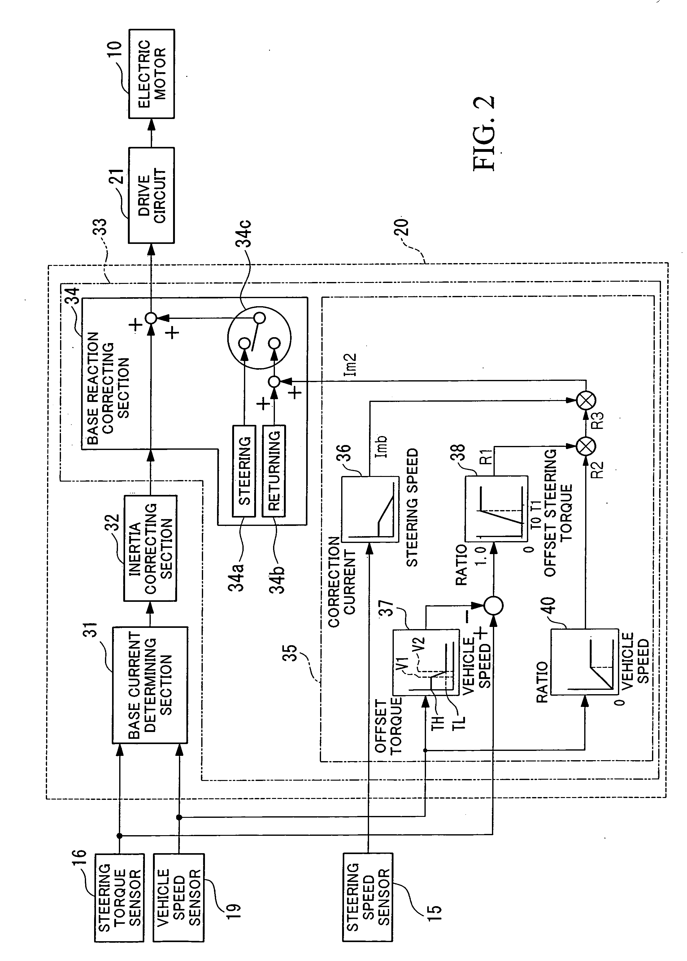
[0015] According to the above structure, basically, the reactive force increases when the steering speed is zero, thereby obtaining (i) a stable feeling for steering when the steered state is maintained, and (ii) higher hysteresis when the steered operating device is returned. In addition, when the steering torque is low (e.g., when lateral acceleration of the vehicle is low), the reactive force applied to the operating device is low, so that assistant steering power by an electric motor can be effectively used when the running state of the vehicle is switched from straight running to turning. Therefore, it is possible to prevent the steering reactive force from decreasing when a steered state is maintained or the steered operating device is returned, thereby improving steering feeling.
[0016] Typically, the reactive force correcting device corrects the reactive force in a manner such that the higher a speed of the vehicle, the higher the corrected reactive force is. Accordingly, when the vehicle turns at a low speed, the reactive force applied to the operating device can be low, thereby effectively using assistant steering power by an electric motor. Conversely, when the vehicle turns at a high speed, the reactive force applied to the operating device can be high, thereby improving stable feeling for the vehicle. Therefore, it is possible to further increase the steering feeling.
[0018] Accordingly, at a relatively high vehicle speed, the reactive force can be high from when the steering torque is relatively low. At a relatively low vehicle speed, the reactive force can be low until when the steering torque becomes relatively high. Therefore, the reactive force to be applied to the operating device can be more appropriately determined in accordance with the vehicle speed, thereby further increasing the steering feeling.

Problems solved by technology

However, in the conventional system in which the driving torque correction value is determined according to the steering speed of the steering wheel, when a steered state is maintained or steering in the opposite direction (i.e., a returning operation) is performed and the steering speed becomes zero, the driving torque correction value indicating the reactive force also becomes zero (i.e., the steering reaction of the steering wheel becomes zero); thus, it is difficult to obtain sufficiently stable feeling for the steering wheel while the steered state is maintained, and hysteresis for returning the steered wheels is low, thereby degrading steering feeling.

Method used


Image

  • Reaction control system for obtaining preferable steering feeling
  • Reaction control system for obtaining preferable steering feeling
  • Reaction control system for obtaining preferable steering feeling

Examples


Embodiment Construction

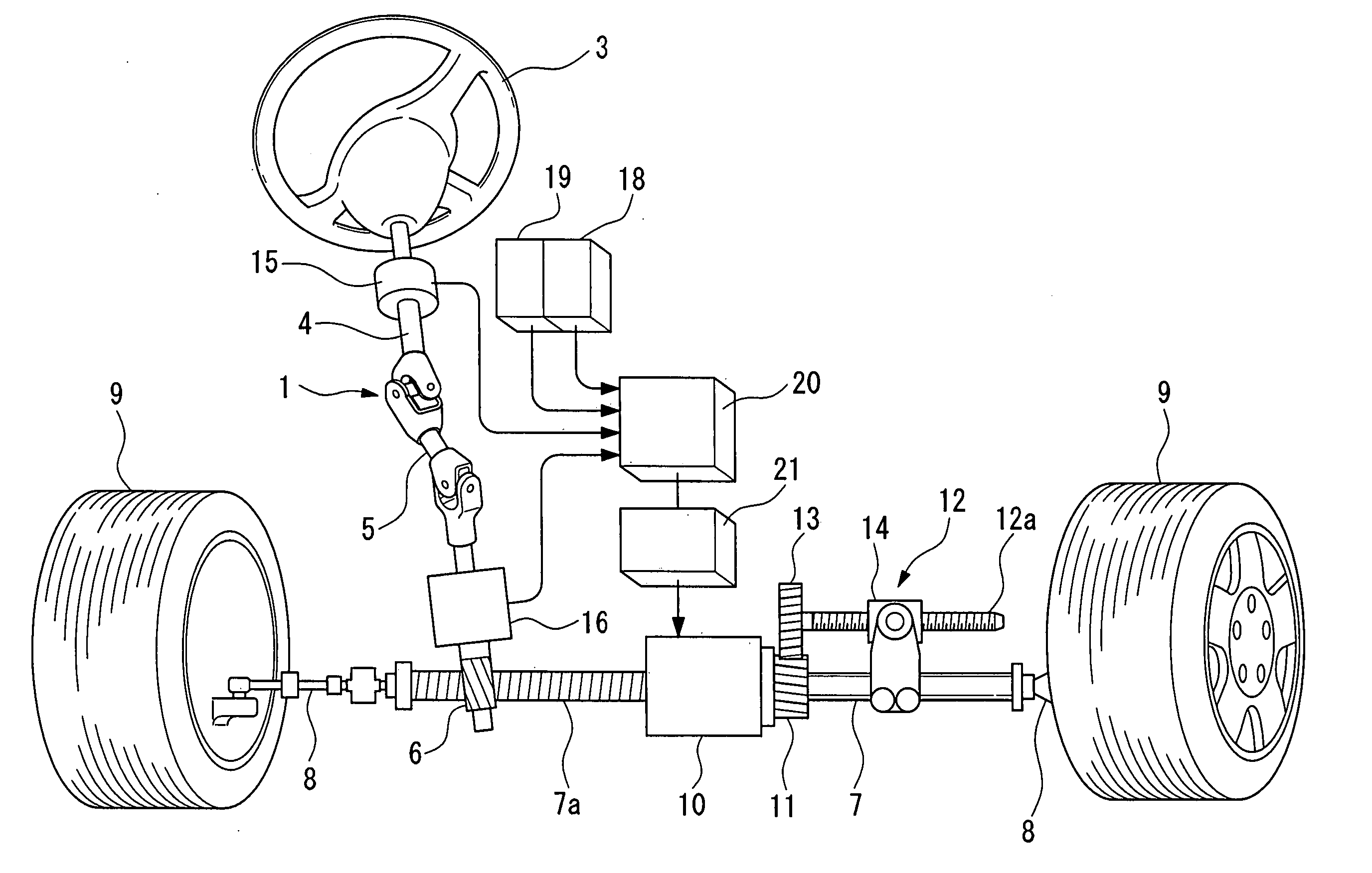
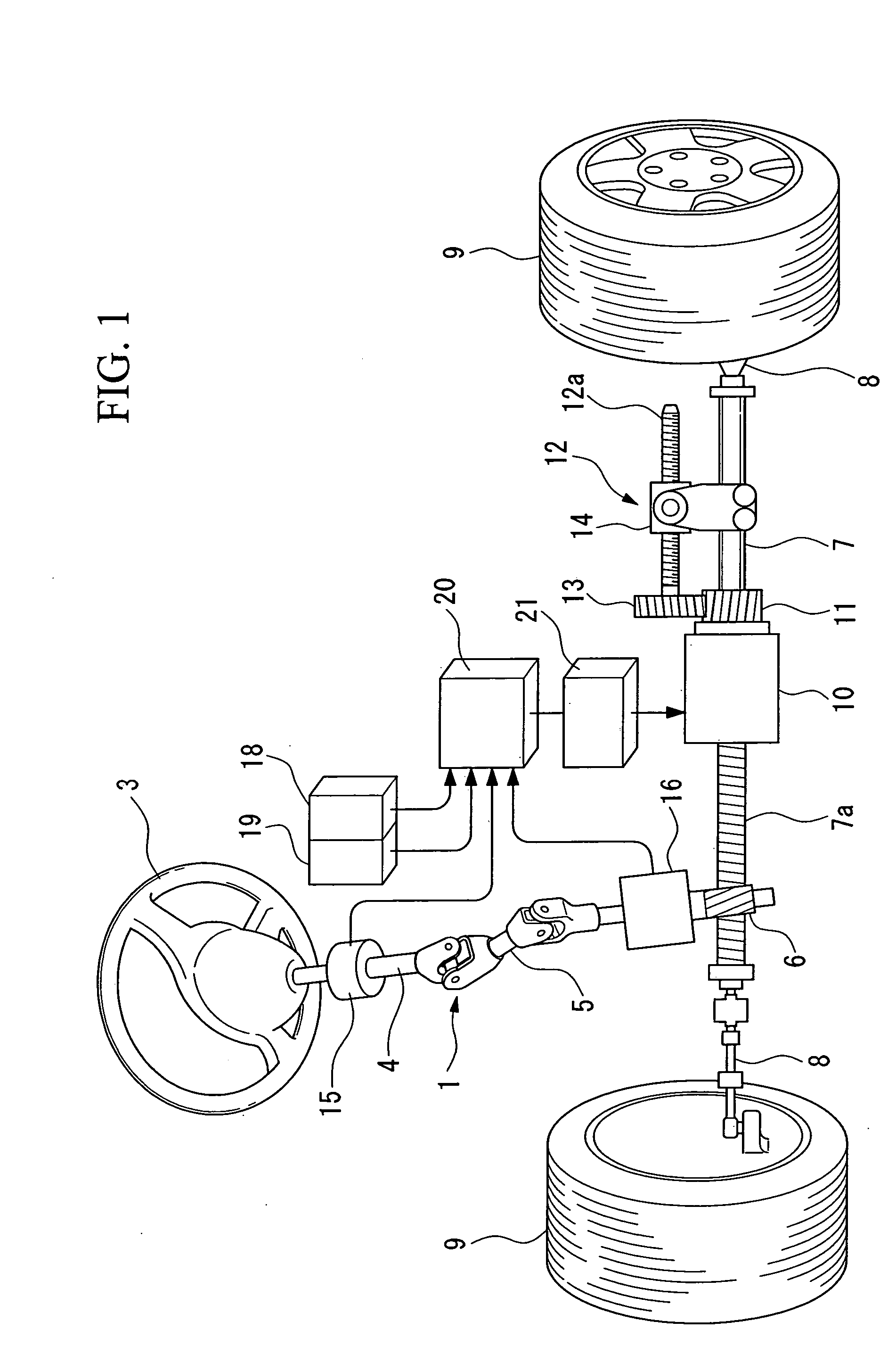
[0023] Hereinafter, an embodiment of the reaction control system according to the present invention will be explained with reference to FIGS. 1 to 3. In the embodiment, the present invention is applied to an electric power steering system.

[0024] First, the structure of the electric power steering system will be explained with reference to FIG. 1. The electric power steering system has a manual steering power generating mechanism 1 in which a steering shaft 4, which is integrally coupled to a steering wheel 3 (i.e., an operating device), is coupled to a pinion 6 of a rack and pinion mechanism by way of a connection shaft 5 which has a universal joint. The pinion 6 is engaged with a rack 7a of a rack shaft 7 which can reciprocate in the axis of the vehicle's width. In addition, front wheels on the vehicle's right and left sides, which are steered wheels, are respectively coupled via tie rods 8 to both ends of the rack shaft 7. According to this structure, normal rack and pinion steer...


PUM


Abstract

A reaction control system controls a reactive force to be applied to an operating device operated by a driver of a vehicle. The system includes a device for measuring a steering speed of steering of the operating device; a device for measuring a steering torque applied to the operating device; and a reactive force correcting device for correcting the reactive force in a manner such that the corrected reactive force increases at least when the measured steering speed is zero, and that the higher the measured steering torque, the higher the corrected reactive force is. The reactive force correcting device may correct the reactive force in a manner such that the higher a speed of the vehicle, the higher the corrected reactive force is. A non-effectivity range of the steering torque in which the corrected reactive force is not influenced by the steering torque may be defined.

Description

BACKGROUND OF THE INVENTION [0001] 1. Field of the Invention [0002] The present invention relates to a reaction control system for controlling a reactive force to be applied to an operating device in a steering system of a vehicle. [0003] Priority is claimed on Japanese Patent Application No. 2004-204523, filed Jul. 12, 2004, the content of which is incorporated herein by reference. [0004] 2. Description of Related Art [0005] As a steering system for a vehicle, an electric power steering system is known. In the electric power steering system, a steering shaft coupled to a steering wheel is mechanically coupled to a steering mechanism for steering steered wheels, and an electric motor for assisting steering power is linked to the steering mechanism. In such an electric power steering system, a driving torque command value for the electric motor (i.e., a current value of current for driving the motor) is controlled in a manner such that the greater the steering torque applied to the s...

Claims


Application Information

Patent Timeline
IPC IPC(8): B62D5/04
CPCB62D6/008
Inventor TAKIMOTO, SHIGENORIYODA, TOSHIHIRO
Owner HONDA MOTOR CO LTD
Why Eureka
Eureka Blog
Learn More