Motor control device

a technology of motor control and control device, which is applied in the direction of program control, dynamo-electric converter control, instruments, etc., can solve the problems of destabilizing steering feeling and driving strangeness, and achieve the effect of holding stable steering feeling

Inactive Publication Date: 2014-12-09
OMRON AUTOMOTIVE ELECTRONICS CO LTD
View PDF15 Cites 3 Cited by
  • Summary
  • Abstract
  • Description
  • Claims
  • Application Information

AI Technical Summary

Benefits of technology

[0010]One or more embodiments of the present invention provides a motor control device capable of suppressing an abrupt change in current offset value, to hold stable steering feeling.
[0012]In such a manner, even when the drift current changes in a large scale, the current offset value does not abruptly change, and is corrected so as to gradually get closer to the target offset value. Hence it is possible to avoid the abrupt change in number of revolutions of the motor in association with the abrupt change in voltage command value, so as to hold stable steering feeling.
[0013]According to one or more embodiments of the present invention, the current detecting unit detects the drift current with respect to each predetermined cycle, and the compensation unit sets a target offset value with respect to each cycle based on a detected current value of the drift current detected by the current detecting unit. In this case, the compensation unit adds a previously set correction value to the current offset value when the current offset value is smaller than the target offset value, and subtracts the correction value from the current offset value when the current offset value is larger than the target offset value, thereby to correct the current offset value with respect to each cycle.
[0017]According to one or more embodiments of the present invention, it is possible to provide a motor control device capable of suppressing an abrupt change in current offset value, to hold stable steering feeling.

Problems solved by technology

Although being a minute current, the drift current has an influence on steering auxiliary force since the current flows during a period when the detected current value should essentially be zero, causing a driver to have a feeling of strangeness in terms of steering feeling.
Accordingly, the number of revolutions of the motor abruptly changes, thus destabilizing the steering feeling,

Method used


Image

  • Motor control device
  • Motor control device
  • Motor control device

Examples


Embodiment Construction

[0028]Hereinafter, embodiments of the present invention will be described with reference to the drawings. In each figure, the same portion or corresponding portion is provided with the same numeral. In embodiments of the invention, numerous specific details are set forth in order to provide a more thorough understanding of the invention. However, it will be apparent to one of ordinary skill in the art that the invention may be practiced without these specific details. In other instances, well-known features have not been described in detail to avoid obscuring the invention.

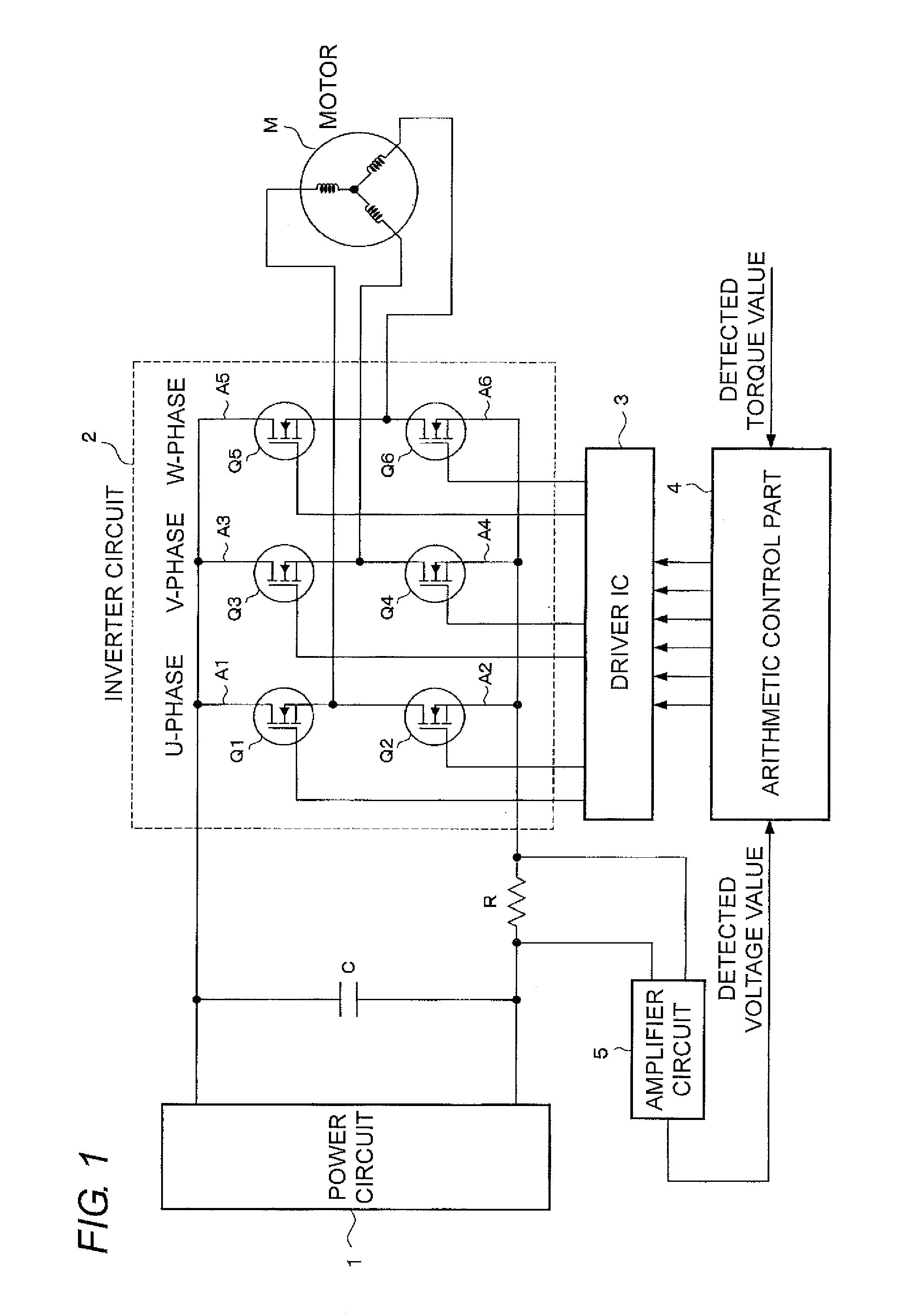
[0029]FIG. 1 shows one example of a motor control device using a PWM control system. A power circuit 1 is configured of a rectifying circuit, a smoothing circuit or the like, and its output end is connected with a capacitor C. The inverter circuit 2 is configured of a three-phase bridge, provided with three pairs of upper and lower arms corresponding to a U-phase, a V-phase and a W-phase. An upper arm A1 of the U-...


PUM


Abstract

A motor control device has a motor driving unit that drives a motor, a current detecting unit that detects a motor current flowing through the motor, a control unit that compares a detected current value of the motor current detected by the current detecting unit with a target current value to obtain a deviation, to control the motor driving unit based on the deviation, and a compensation unit that sets as a current offset value a detected current value of a drift current detected by the current detecting unit in a state where the motor current is regarded as zero, to compensate the detected current value of the motor current by the current offset value. The compensation unit sets a target offset value according to the current value of the detected drift current to correct the current offset value stepwise until the current offset value reaches the target offset value.

Description

TECHNICAL FIELD[0001]The present invention relates to a motor control device for detecting a current flowing through a motor, to control the motor based on a deviation between a detected current value and a target current value, and particularly relates to a technique for compensating a drift current that is detected in a state where the motor current is regarded as zero.BACKGROUND ART[0002]In an electric power steering device of a vehicle, an electric motor such as a blushless motor is provided for providing a steering mechanism with steering auxiliary force in accordance with a steering torque of a wheel. As a device for driving this motor, there is known a motor control device using a PWM (Pulse Width Modulation) control system.[0003]Generally, the motor control device using the PWM control system is provided with an inverter circuit and a control part for controlling this inverter circuit. The inverter circuit is provided with a plurality of pairs (three pairs in the case of a t...

Claims


Application Information

Patent Timeline
Patent Type & Authority Patents(United States)
IPC IPC(8): G05B19/408H02P27/08H02P6/08H02P6/06H02P6/28
CPCH02P2205/01H02P27/08
Inventor YABUGUCHI, MICHISADAFUKUMOTO, TETSUYANAKAMURA, TAKENOBU
Owner OMRON AUTOMOTIVE ELECTRONICS CO LTD
Why Eureka
Try Eureka