Clutch control method

a technology of clutch connection and control method, which is applied in the direction of rotary clutches, interengaging clutches, fluid couplings, etc., can solve the problems of insufficient simple modification of clutch connection methods, inconvenience of unstable feel, and driver not knowing when to step on the accelerator

Inactive Publication Date: 2003-01-02
ISUZU MOTORS LTD
View PDF10 Cites 3 Cited by
  • Summary
  • Abstract
  • Description
  • Claims
  • Application Information

AI Technical Summary

Problems solved by technology

When connection of the clutch is too rapid, this produces a clutch connection shock (so-called "garage shock" or similar), and when the clutch connection is too slow, it takes time from the gear-in operation until the generation of creep, and the driver does not know when to step on the accelerator (large time lag).
However, as a result of individual differences, such as variations in the torque point learning value, in the clutch characteristics, or in the oil temperature, and the like, and/or deviations in the usage conditions, problems occurred such as the generation of clutch con

Method used


Image

  • Clutch control method
  • Clutch control method
  • Clutch control method

Examples


Embodiment Construction

[0042] A preferred embodiment of the present invention will be described hereinbelow with reference to the attached drawings.

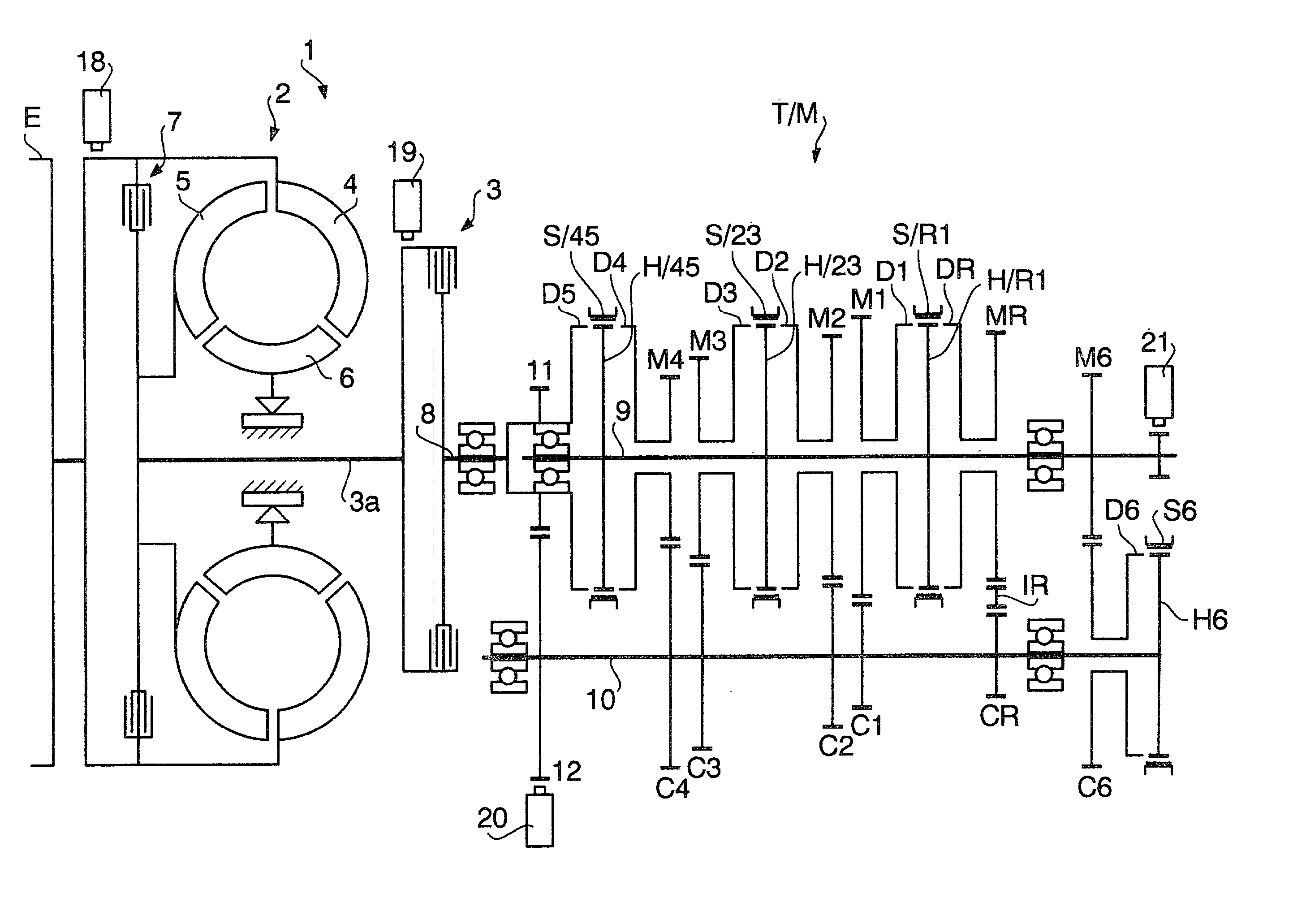
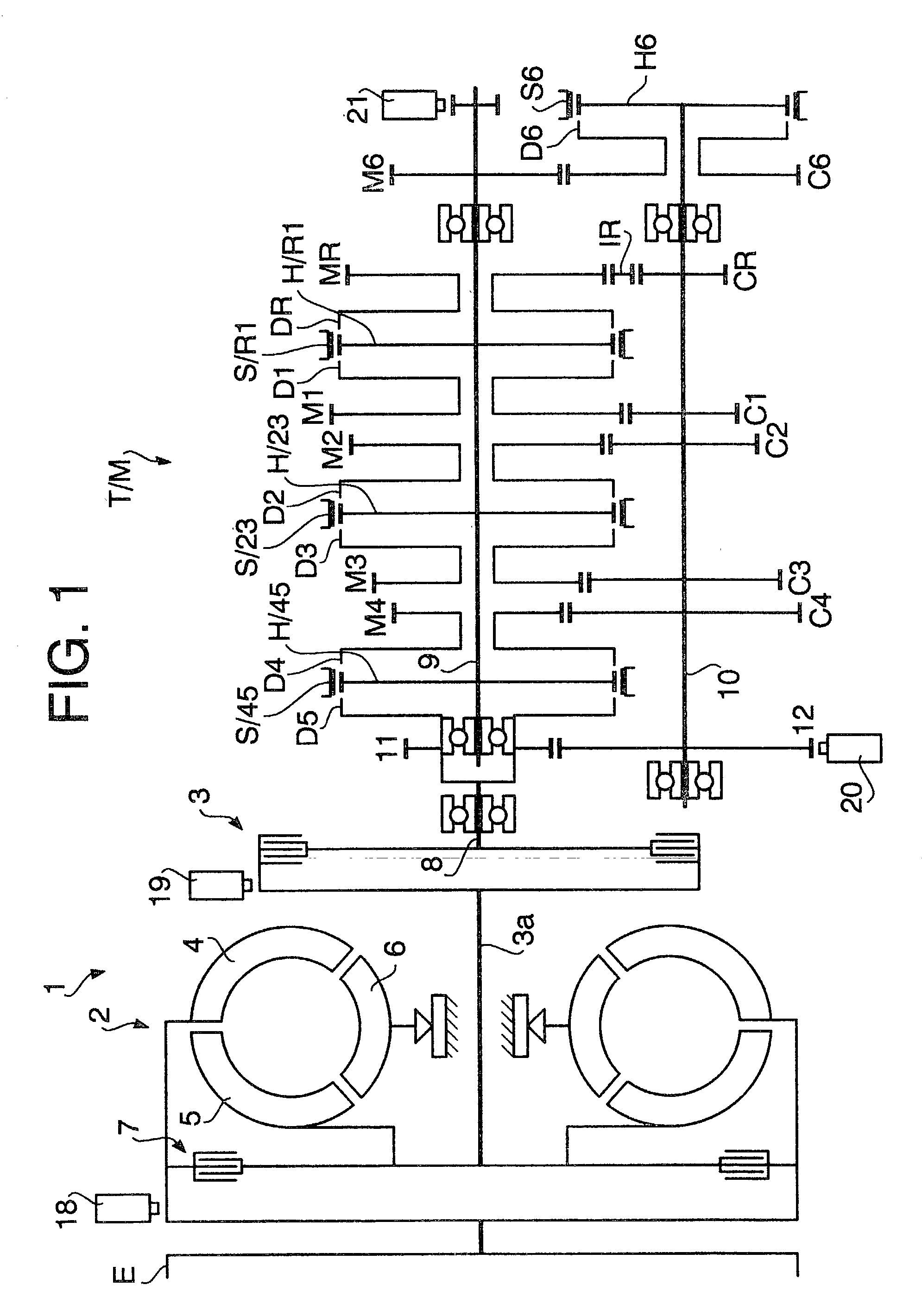
[0043] FIG. 1 shows a power transmission device of a vehicle, according to the present embodiment. As shown by the figure, a clutch mechanism 1 is provided between the engine E and the transmission T / M, and the clutch mechanism 1 is constituted from a fluid coupling 2, which is provided upstream in the power transmission direction; and, provided serially downstream therefrom, a wet multi-plate clutch 3 serving as a wet friction clutch. Also, the fluid coupling here is a broad concept comprising a torque converter, and a torque converter is actually also used in the present embodiment. A vehicle to which the present invention is applied is a relatively large vehicle with tracks, or similar. The engine E is a diesel engine.

[0044] The fluid coupling 2 has a pump 4, which is connected to the output shaft (crank shaft) of the engine; a turbine 5, which faces toward...


PUM


Abstract

The present invention provides a clutch connection method which controls the disconnection/connection of a wet friction clutch on the basis of a duty pulse outputted from an electronic control unit. When the clutch is connected, the electronic control unit initially outputs a start duty (Dst) for largely connecting the clutch as far as the vicinity of a torque point, and, thereafter, outputs, at prescribed time intervals (DELTAt), a gradual connection duty (Dk) for gradually connecting the clutch, and determines a gradual connection duty value on the basis of a clutch input/output side revolution difference DELTAN. Since the clutch is gradually connected while monitoring the clutch connection state, variations between connection times and connection shock, resulting from individual clutch differences or the like, can be eliminated, whereby it is possible to achieve a stable feel. Further, in control which connects the clutch in sync with completion of a transmission gear shift, a plurality of clutch connection modes (an engine plus mode, an in-shaft plus mode, and a synchro mode) are preset, and the clutch connection modes are selected in accordance with the size of clutch input-side and output-side revolution numbers upon completion of a gear shift. Clutch connection is performed which conforms to actual conditions since a clutch connection mode is selected in accordance with the size of clutch input/output side revolution numbers rather than with respect to a shift-up or a shift-down.

Description

[0001] This application is entitled to the benefit of and incorporates by reference essential subject matter disclosed in Japanese Patent Applications No. 2001-199269 filed Jun. 29, 2001 and No. 2001-199270 filed Jun. 29, 2001.[0002] 1. Field of the Invention[0003] The present invention relates to a clutch control method, and more particularly to a method for controlling the connection / disconnection of a wet friction clutch which is provided in a power transmission system of a vehicle.[0004] 2. Description of the Related Art[0005] The present inventors have newly developed a vehicle power transmission device, in which a fluid coupling capable of being locked up (including a torque converter) and a wet friction clutch are serially provided between the engine and transmission, and which automatically connects and disconnects the wet friction clutch during transmission. Here, if the vehicle is put into gear while stationary, the clutch is subsequently automatically connected, and creep...

Claims


Application Information

Patent Timeline
IPC IPC(8): F16D48/06
CPCB60W2510/0241B60W2510/0638B60W2510/1005B60W2510/1015F16D48/066F16D2500/10412F16D2500/1045F16D2500/1068F16D2500/30406F16D2500/3067F16D2500/30806F16D2500/30816F16D2500/3108F16D2500/31426F16D2500/31466F16D2500/31473F16D2500/31493F16D2500/3166F16D2500/50239F16D2500/50293F16D2500/525F16D2500/70406F16D2500/7109
Inventor INOUE, EIJISHINOJIMA, TAKUMI
Owner ISUZU MOTORS LTD
Why Eureka
Try Eureka