Disk brake device

a disc brake and disc brake technology, applied in the direction of brake systems, mechanical equipment, transportation and packaging, etc., can solve the problems of difficult to correct the clearance to the predefined value, the piston cannot be retracted appropriately, and the piston cannot be stably retracted, so as to achieve stable brake feeling, reduce friction pad drag, and return stably

Active Publication Date: 2013-03-21
TOYOTA JIDOSHA KK
View PDF9 Cites 5 Cited by
  • Summary
  • Abstract
  • Description
  • Claims
  • Application Information

AI Technical Summary

Benefits of technology

[0025]Accordingly, the reversing force transferring means is stroked in the retreating direction relative to the advancing piston due to, for example, the reversing force generated by the reversing means to compress and deform the restoring force imparting means, with the result that the restoring force generated against the deformation can be imparted to the advanced piston. Thus, the restoring force can be imparted constantly from the advancing position of the piston, and hence the piston can be returned stably. Therefore, the friction pads are returned to positions with a predetermined clearance from the disc rotor, with the result that the drag phenomenon of the friction pads can be suppressed, and a stable brake feeling can be obtained.
[0026]Further, the restoring force can be imparted constantly from the advancing position of the piston. Therefore, for example, there is no need to adjust the returning amount (that is, retracting amount) of the piston for each vehicle, and the development cost can be reduced as well.
[0027]Further, the retraction mechanism may be provided to the piston, and hence there is no need to perform processi...

Problems solved by technology

When the brakes are applied in this state, the position of the retraction ring is not stable, which may hinder the piston from retracting stably.
Therefore, even when the drag phenomenon occurs, it may be difficult to eliminate the drag phenomenon, and further, when a clearance larger than a predefined value is formed between the piston and the pad (disc rotor), it may be difficult to correct t...

Method used


Image

  • Disk brake device
  • Disk brake device
  • Disk brake device

Examples


first embodiment

a. First Embodiment

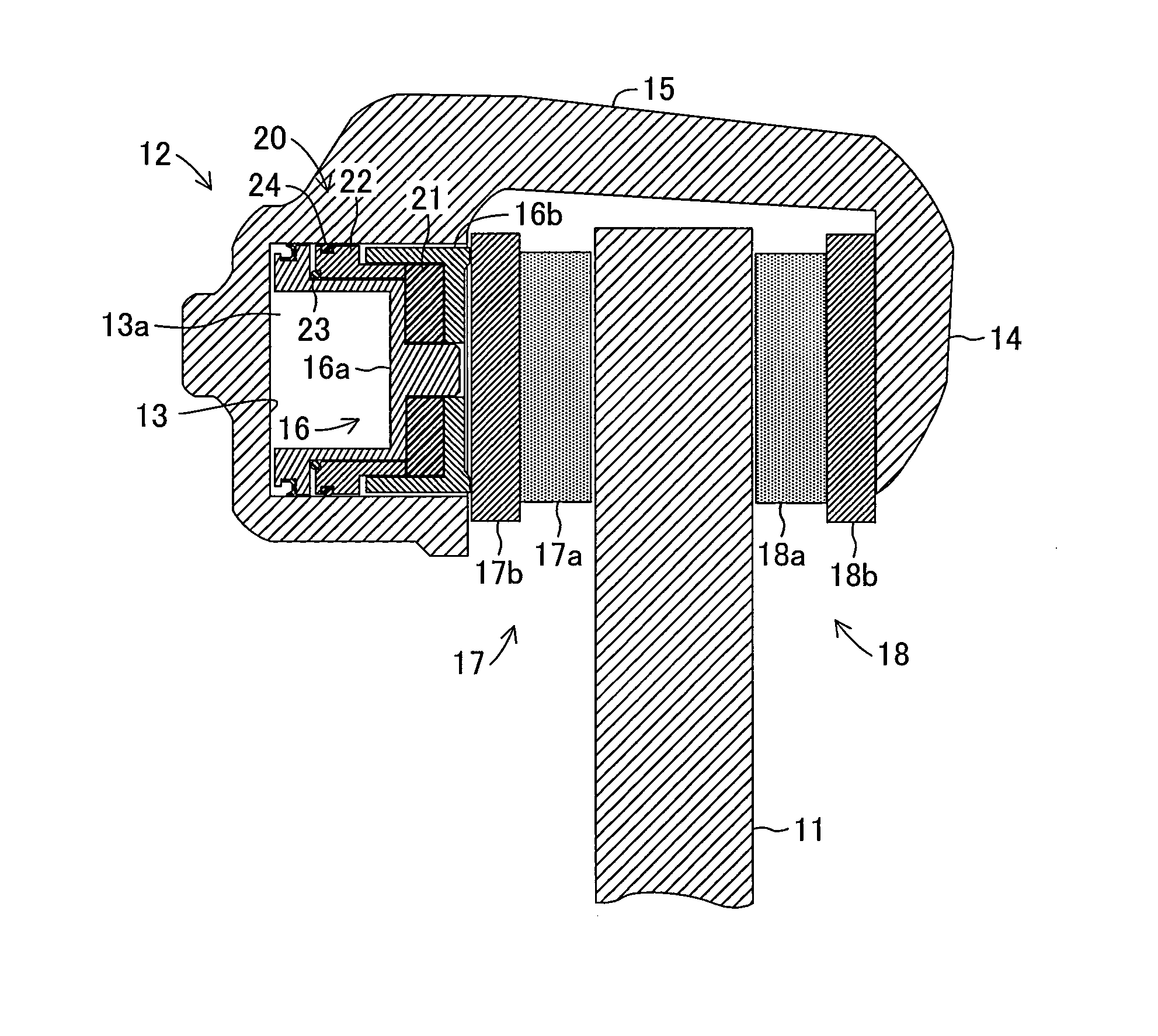
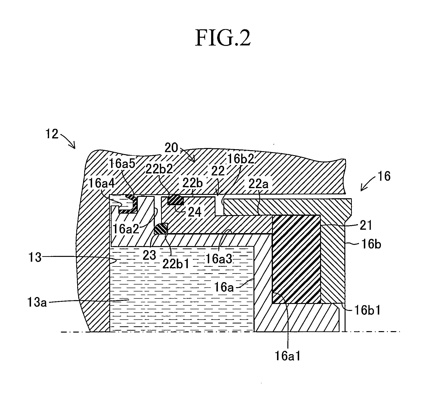
[0055]In the following, embodiments of the present invention are described in detail with reference to the drawings. FIG. 1 schematically illustrates a floating caliper disc brake device which is common to the respective embodiments of the present invention.

[0056]The disc brake device includes a disc rotor 11 which rotates integrally with a wheel (not shown) about a rotational axis of an axle, and a caliper 12 which is supported by a mounting bracket (not shown) fixed to a vehicle body side so as to be movable along a rotational axis direction of the disc rotor 11.

[0057]The caliper 12 has a substantially U-shaped cross section astride the disc rotor 11, and includes a cylinder portion 13 which is supplied with a brake fluid in response to a braking operation performed by a driver, a claw portion 14 arranged at a position opposed to the cylinder portion 13 through an intermediation of the disc rotor 11, and a coupling portion 15 for coupling the cylinder portion 13...

third modification example

d. Third Modification Example of First Embodiment

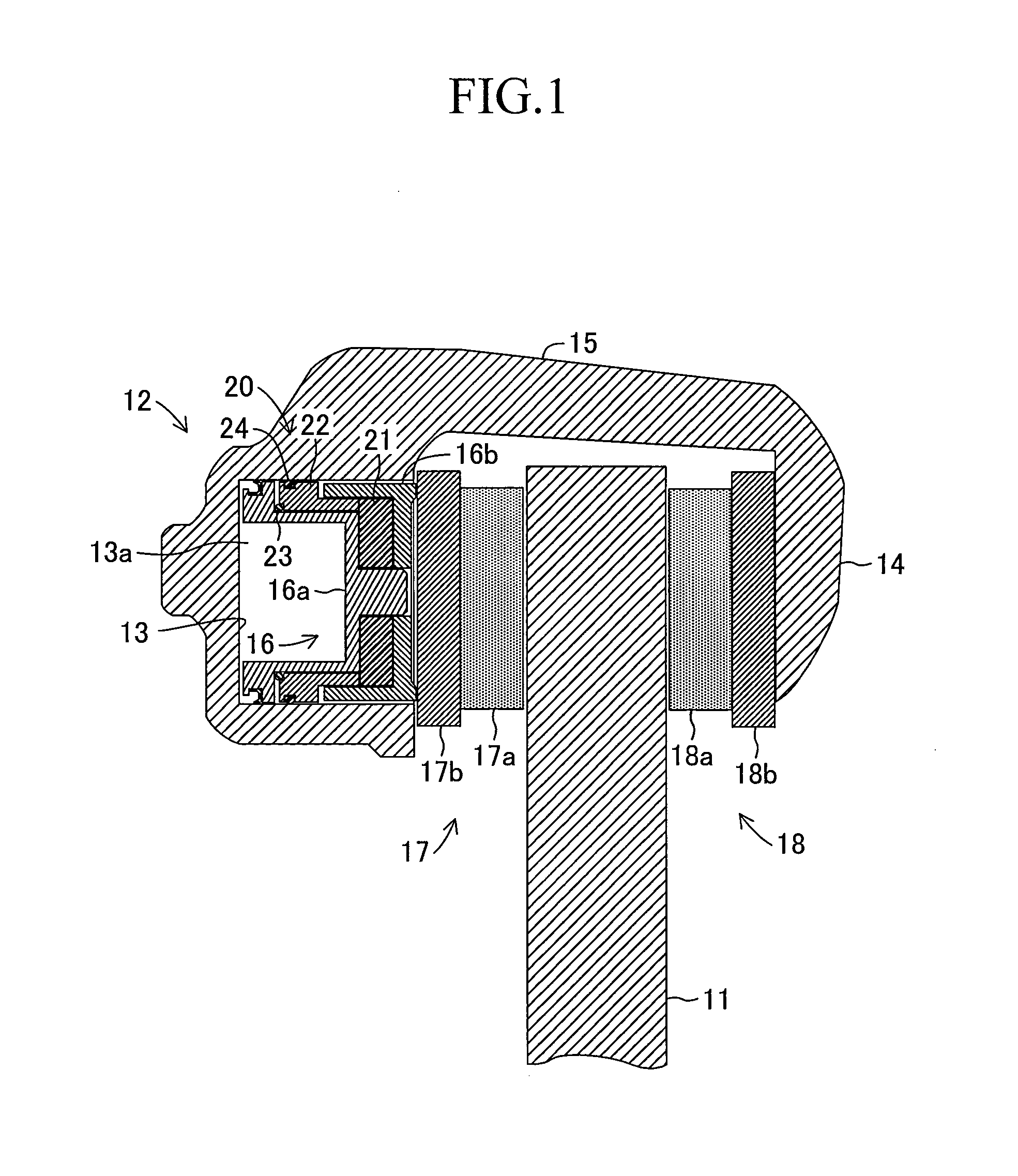
[0118]In the first embodiment described above, the present invention is carried out in the following manner. That is, in the retraction mechanism 20, the reversing member 21 made of the viscoelastic material is employed, and the reversing member 21 imparts, to the movable element 22, the reversing force which is generated through the compression by the first stepped portion 16a1 of the pressure receiving portion 16a. In this case, the present invention may be carried out in such a manner that, instead of employing the reversing member 21 made of the viscoelastic material, the advancing stroke of the advancing pressure receiving portion 16a is mechanically reversed and the retreating stroke (that is, reversing force) is imparted to the movable element 22. In the following, a third modification example of the first embodiment is described in detail, but the same components as those in the first embodiment described above are represented...

second embodiment

e. Second Embodiment

[0132]In the first embodiment and its modification examples described above, the present invention is carried out in the following manner. That is, the reversing members 21, 31, 41, and 51 generate the reversing force (or the retreating stroke) along with the advance of the pressure receiving portion 16a and the first pressure receiving portion 16c, to thereby generate the restoring force for returning the piston 16 with use of the reversing force (or the retreating stroke). The present invention may be carried out in such a manner that, instead of generating the reversing force (or the retreating stroke) through use of the reversing members 21, 31, 41, and 51 as described above, the brake fluid pressure in the hydraulic pressure chamber 13a is directly used for generating the reversing force (or the retreating stroke). In the following, a second embodiment of the present invention is described in detail, but the same components as those in the first embodiment d...


PUM


Abstract

A cylinder portion (13) formed in a caliper (12) supports a pressure receiving portion (16a) and a pressing portion (16b) of a piston (16) so as to allow the pressure receiving portion (16a) and the pressing section (16b) to advance and retreat. The piston (16) is provided with a retraction mechanism (20). The retraction mechanism (20) includes a reversing member (21) for generating a reversing force when compressed by the pressure receiving portion (16a) and the pressing portion (16b). The mechanism (20) further includes a movable element (22) moved in a retreating stroke due to the reversing force, and a first elastic member (23) for generating a restoring force and imparting the restoring force, the first elastic member (23) generating the restoring force when compressed by the movable element (22) and the pressure receiving portion (16a) which is moved in an advancing stroke. The mechanism (20) further includes a second elastic member (24) for generating a frictional force for maintaining the compression and deformation of the first elastic member. The reversing member (21) generates the reversing force along with the advance of the pressure receiving portion (16a), the movable element (22) relatively retreats due to the reversing force and compresses the first elastic member (23), and the generated restoring force returns the pressure receiving portion (16a) and the pressing portion (16b) along with a decrease in pressure of a brake fluid.

Description

TECHNICAL FIELD[0001]The present invention relates to a disc brake device for applying a braking force to a wheel via a disc rotor using a frictional resistance generated by squeezing the disc rotor rotating integrally with the wheel through use of friction pads provided to a caliper.BACKGROUND ART[0002]In a general floating caliper disc brake device, a caliper arranged astride a disc rotor is supported on a mounting bracket. Further, a pair of slide pins is provided to the caliper, and fitting holes to which the pair of slide pins is slidably fitted are provided to the mounting bracket. Accordingly, the slide pins slide along the fitting holes so that the caliper is movable in a rotational axis direction of a wheel. In addition, an inner pad (friction pad) is movably supported on one side of the caliper, and an outer pad (friction pad) is fixed on the other side thereof. Moreover, a piston and a cylinder are provided to the caliper so as to press the inner pad on one side against t...

Claims


Application Information

Patent Timeline
IPC IPC(8): B60T1/06F16D55/226F16D65/18
CPCF16D55/226F16D65/18B60T1/06F16D2125/06F16D2127/02F16D2121/02
Inventor ISONO, HIROSHI
Owner TOYOTA JIDOSHA KK
Why Eureka
Try Eureka