Detachable connector and front-panel device including same

a detachable connector and front-panel technology, applied in the direction of flexible/turnable line connectors, coupling device connections, coupling parts engagement/disengagement, etc., can solve the problems of reducing the reliability of the electrical connection between the male connector unit and the female connector unit, increasing the risk of pushing the convex contact in an undesired direction, and avoiding the effect of slipping

Active Publication Date: 2007-01-30
ALPINE ELECTRONICS INC
View PDF11 Cites 19 Cited by
  • Summary
  • Abstract
  • Description
  • Claims
  • Application Information

AI Technical Summary

Benefits of technology

[0010]Accordingly, it is an object of the present invention to provide a detachable connector capable of maintaining a required terminal contact pressure without causing an excessive reaction force to be applied on a male connector unit attached to a female connector unit and capable of avoiding damage to the female terminal in the process of separation of the male connector unit from the female connector unit and to provide a front-panel device including the detachable connector.
[0012]As described above, when, in a pair of the female terminals in the female connector unit in the main body, the first female terminal that has a longer distance to the axis of rotation of the movable panel includes the sloped portion for being in contact with the convex contact from obliquely above in an elastic manner, the convex contact can smoothly escape in the process of separation of the male connector unit from the female connector unit. As a result, the detachable connector prevents the first female terminal from being damaged, thus increasing the longevity of the detachable connector. Additionally, when the second female terminal that has a shorter distance to the axis of rotation of the movable panel includes the contact portion for being in contact with the convex contact from a side in an elastic manner, if a position where the sloped portion is in contact with the convex contact in an elastic manner is more distant from the movable panel in the main body than a position where the contact portion is in contact with the convex contact in an elastic manner, a reaction force of pushing the convex contact in a direction in which the convex contact is ejected is reduced by a friction force produced by the contact portion. Therefore, a required terminal contact pressure can be maintained without causing an excessive reaction force to be applied on the male connector unit being attached to the female connector unit. As a result, the reliability of an electrical connection is assured, and the movable panel and the locking means for locking the movable panel are prevented from being plastically deformed.
[0013]In the structure described above, the sloped portion may be disposed adjacent to a free end of the first female terminal, and a leading-end corner of the convex contact inserted into the insertion path may slide on the sloped portion toward a section adjacent to the free end in the sloped portion. This is preferable because the sloped portion, which is in contact with the adjacent section of the leading end of the convex contact inserted into the insertion path in an elastic manner with reliability and which avoids the possibility of interfering with the operation of ejecting the convex contact, is easily created.
[0014]According to an embodiment of the present invention, in first and second female terminals, a first female terminal which has a longer distance to an axis of rotation of a movable panel includes a sloped portion for being in contact with a convex contact of a male connector unit mounted to the movable panel in an elastic manner from obliquely above. This allows the convex contact to smoothly escape in the process of separating of the male connector unit. Additionally, the second female terminal which has a shorter distance to the axis of rotation of the movable panel includes a closed position for being in contact with the side surface of the convex contact in an elastic manner. This prevents the terminal contact pressure of the contact portion from functioning as a reaction force for pushing the convex contact in a direction in which the convex contact is ejected. Furthermore, a position where the sloped portion is in contact with the convex contact in an elastic manner is set so as to be more distant from the movable panel in the main body than a position where the contact portion is in contact with the convex contact in an elastic manner, and therefore, the reaction force of pushing the convex contact in a direction in which the convex contact is ejected is reduced by a friction force at the contact portion.
[0015]In a detachable connector according to the embodiment of the present invention, a pair of female terminals is not substantially symmetrically disposed with respect to a line. A first female terminal includes a sloped portion for being obliquely in contact with a convex contact of a male connector unit mounted to a movable panel in an elastic manner so that the convex contact can smoothly escape. Additionally, a second female terminal includes a contact portion for being in contact with the convex contact from a side in an elastic manner so that the convex contact will not be excessively pushed in a direction in which the convex contact is ejected in the process of attachment of the male connector unit to the female connector unit. Therefore, a required terminal contact pressure is maintained without causing an excessive reaction force to be applied on the male connector unit being attached to the female connector unit. Therefore, the reliability of an electrical connection is assured, and the movable panel and the locking means for locking the movable panel are prevented from being damaged. At the same time, the female terminal is prevented from being plastically deformed in the process of separating of the male connector unit from the female connector unit, thus increasing the longevity of the detachable connector.

Problems solved by technology

However, this approach reduces the reliability of the electrical connection between the male connector unit and the female connector unit.
However, according to this approach, in the process of separating the male connector unit from the female connector unit, elastically contacted members of female terminals that have a longer distance to the axis of rotation of the movable panel, in the first female terminals and second female terminals, than the others cannot smoothly escape the convex contacts rotating integrally with the movable panel.
This increases the risk of pushing the convex contacts in an undesired direction.
As a result, another problem arises in which the relevant female terminals are prone to be damaged.

Method used


Image

  • Detachable connector and front-panel device including same
  • Detachable connector and front-panel device including same
  • Detachable connector and front-panel device including same

Examples


Embodiment Construction

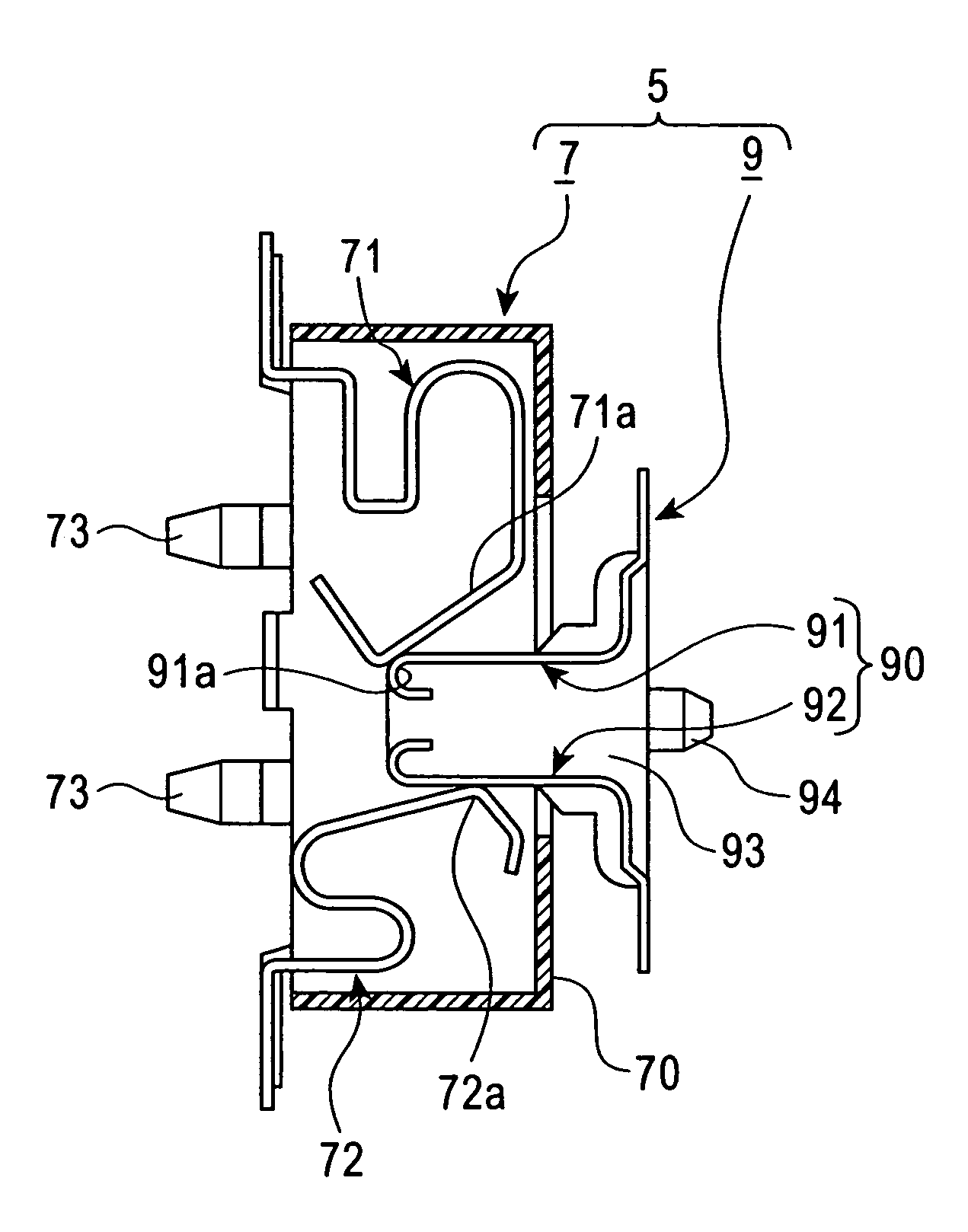
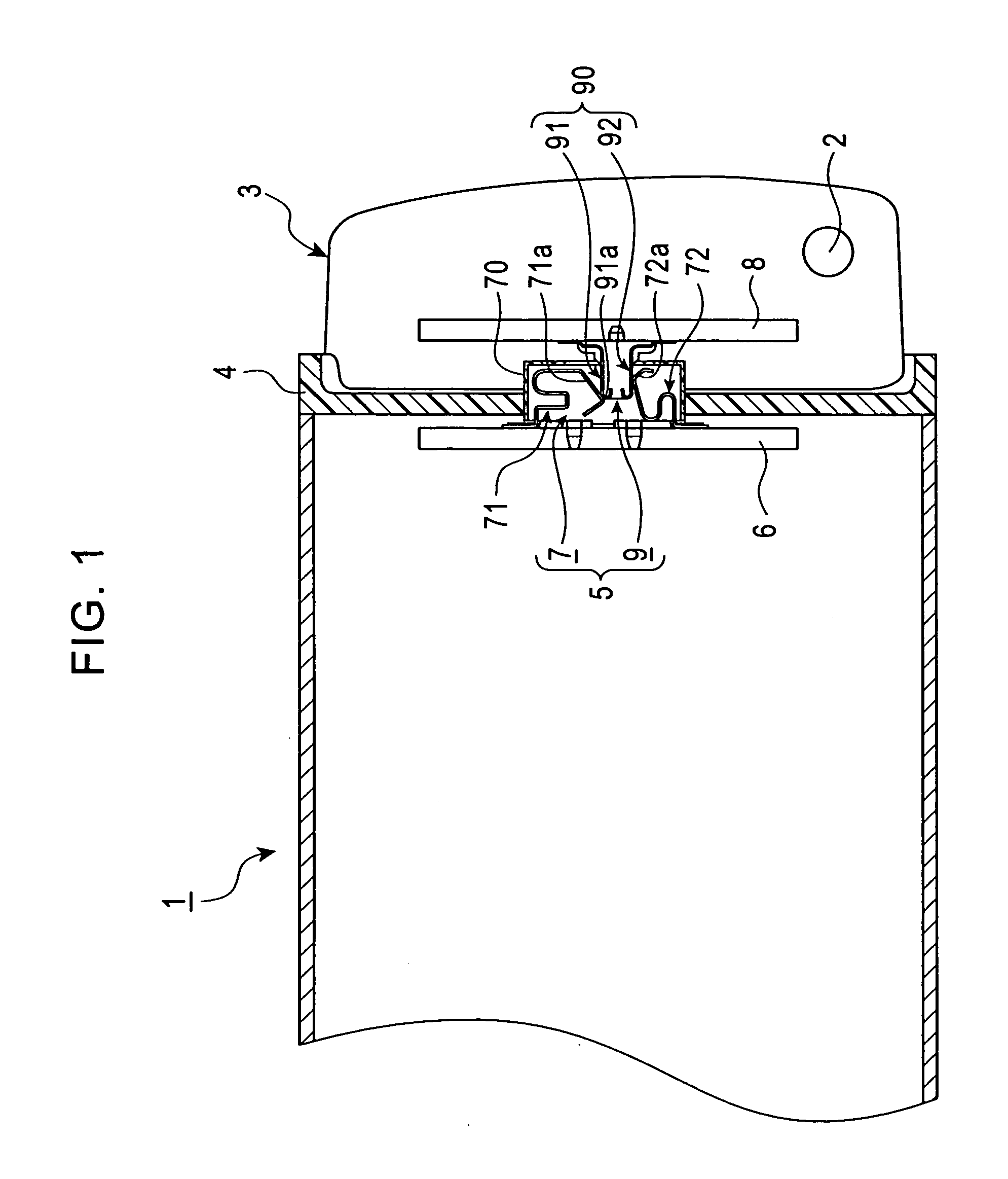
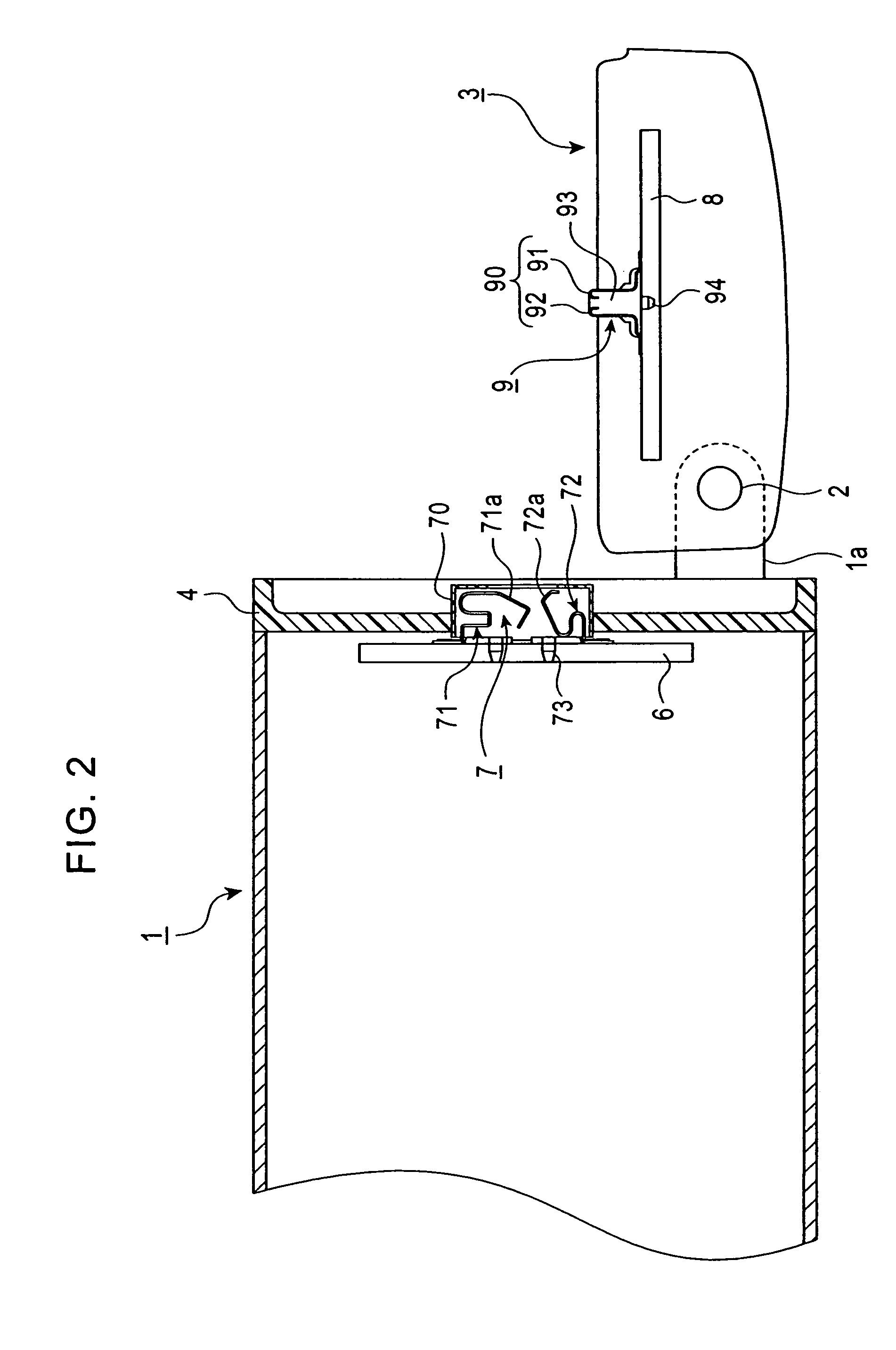
[0026]In a front-panel device in a vehicle-mounted electronic apparatus shown in FIGS. 1 and 2, a movable panel 3 is detachably and rotatably mounted on a supporting shaft 2 mounted on an arm 1a of a main body 1 of the apparatus. The main body 1 includes a loading slot (not shown) for inserting and ejecting a medium (e.g., MD or CD) formed at a front portion 4. At the movable panel 3, a display screen (not shown) and various operating keys (not shown) are arranged. The main body 1 and movable panel 3 are electrically connected to each other with a detachable connector 5 disposed therebetween. The detachable connector 5 includes a female connector unit 7 connected to a circuit board 6 incorporated in the main body 1 and a male connector unit 9 connected to a circuit board 8 incorporated in the movable panel 3.

[0027]As shown in FIGS. 3 and 4, the female connector unit 7 includes a synthetic-resin cover 70 having a window 70a, first female terminals 71 each including a sloped portion 7...


PUM


Abstract

A detachable connector is provided in which a male connector unit mounted to a movable panel is attachable to and detachable from a female connector unit mounted to a main body. In a pair of first and second female terminals, the first female terminal which has a longer distance to an axis of rotation of the movable panel includes a sloped portion for being elastically in contact with a leading-end corner of a convex contact of the male connector unit from obliquely above, and the second female terminal includes a contact portion for being elastically in contact with the side surface of the convex contact from below. When the male connector unit is attached to the female connector unit, the sloped portion is in contact with the convex contact at a position that is more distant from the movable panel than the contact portion.

Description

BACKGROUND OF THE INVENTION[0001]1. Field of the Invention[0002]The present invention relates to a detachable connector that is included in a front-panel device in which a front portion of a main body is openable / closable by a movable panel rotatably mounted to the main body and that is capable of attaching a male connector unit to a female connector unit and detaching the male connector unit from the female connector unit with the rotation of the movable panel.[0003]2. Description of the Related Art[0004]For a vehicle-mounted electronic apparatus, such as a mini disk (MD) player or compact disk (CD) player, in order to reduce the size and profile of the electronic apparatus and to ensure a required space for arranging a display screen of, for example, a liquid crystal display and various operating keys, a front-panel device is known in which a front portion of a main body of the apparatus is formed so as to be openable / closable by a rotatably mounted movable panel. In the front-pan...

Claims


Application Information

Patent Timeline
Patent Type & Authority Patents(United States)
IPC IPC(8): H01R24/00
CPCH01R35/04H01R13/2442
Inventor SANO, NORIYUKI
Owner ALPINE ELECTRONICS INC
Why Eureka
Try Eureka