

Liquid ejection head and flexible wiring substrate used in liquid ejection head
a technology of liquid ejection and flexible wiring substrate, which is applied in the direction of printed circuits, printed circuit details, printing, etc., can solve the problems of large reaction force that causes the bent portion to return to the original state from the bent state, and it is difficult to maintain the flexible wiring substrate in a bent state. , to achieve the effect of reducing the risk of the bent portion
- Summary
- Abstract
- Description
- Claims
- Application Information
AI Technical Summary
Benefits of technology
Problems solved by technology
Method used
Image

Examples
first embodiment
[0027]Next, the flexible wiring substrate 14 according to a first embodiment of the present invention will be described. FIGS. 4A to 4C are plan views of the flexible wiring substrate 14 according to the first embodiment. Wiring lines arranged in the flexible wiring substrate 14 are indicated by dashed lines. In FIGS. 4A to 4C, part of the wiring lines located beneath a tape-like base member 401 of the flexible wiring substrate 14 are indicated by solid lines to show the positional relationship between real wiring lines and dummy wiring lines (described below).
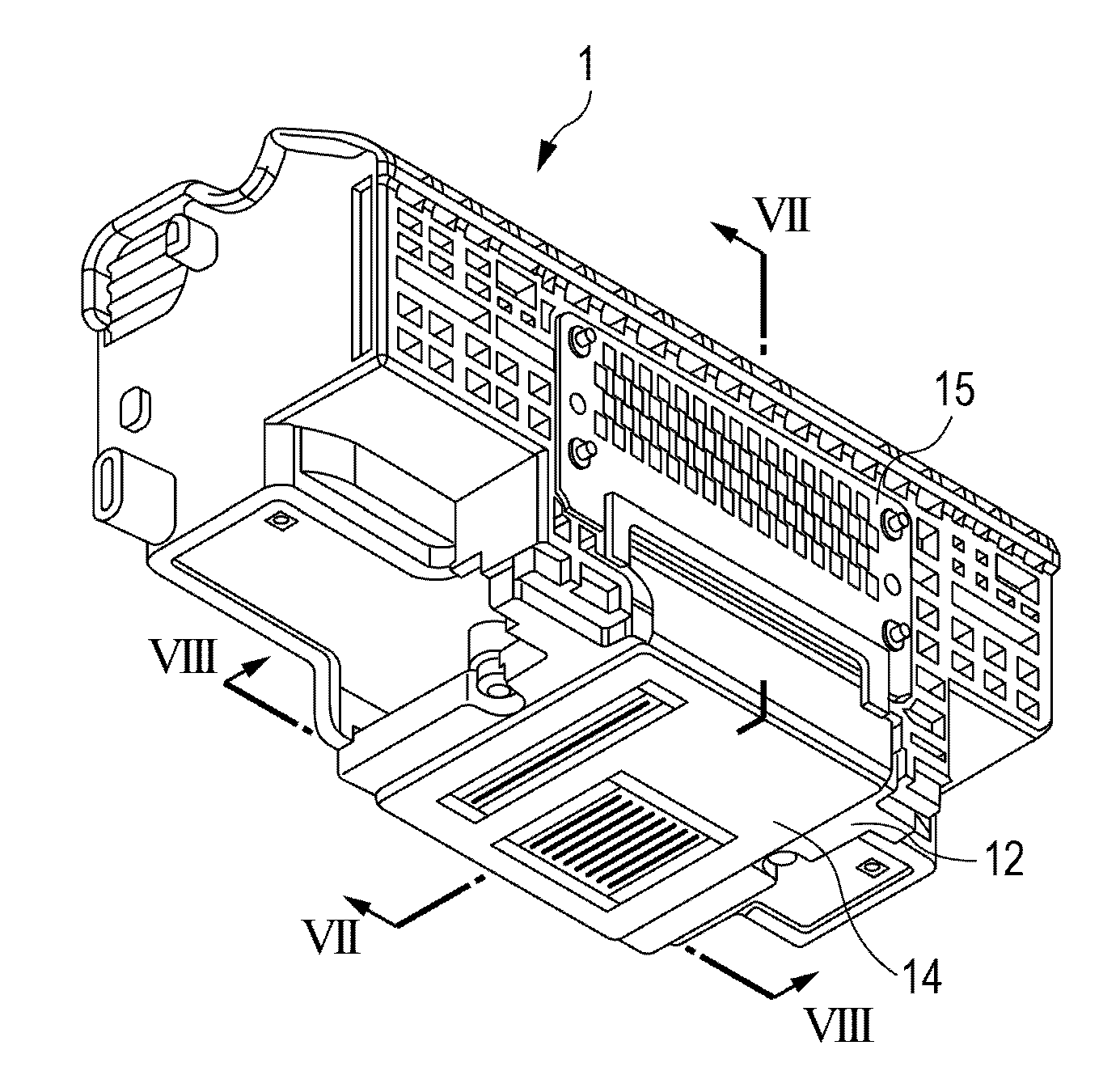
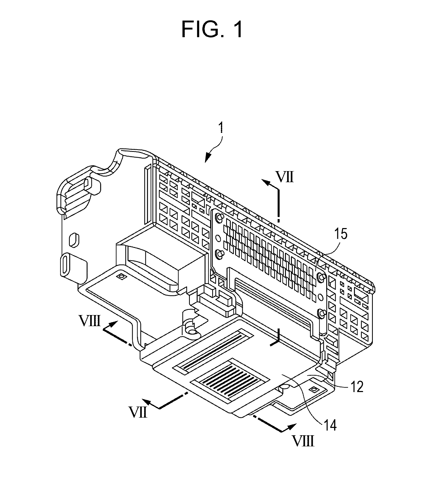
[0028]FIG. 8 is a sectional view of a part of the flexible wiring substrate 14 and the second plate 13, taken along line VIII-VIII in FIG. 1. Referring to FIG. 8, the configuration of the flexible wiring substrate 14 will be described in detail. The flexible wiring substrate 14 according to this embodiment is composed of, for example, a tape automated bonding (TAB) tape, in which wiring lines 404 composed of copper foil is dis...
second embodiment
[0041]FIG. 5 is a plan view of the flexible wiring substrate 14 according to a second embodiment of the present invention. The wiring lines provided in the flexible wiring substrate 14 are indicated by dashed lines. In FIG. 5, part of the wiring lines located beneath the tape-like base member 401 of the flexible wiring substrate 14 are indicated by solid lines to show the positional relationship between the real wiring lines and the dummy wiring lines.
[0042]Also in this embodiment, similarly to the first embodiment, at the bending portion 14b of the flexible wiring substrate 14, the dummy wiring lines 404b are provided in the area in which the real wiring lines 404a, which are electrically connected to the recording elements of the recording-element substrates 11, are not provided. This configuration makes it easy to maintain the bending portion 14b of the flexible wiring substrate 14 in a bent state and makes it possible to reduce a risk of the bending portion projecting outward an...
third embodiment
[0050]FIG. 6 is a plan view of the flexible wiring substrate 14 according to a third embodiment of the present invention, in which the wiring lines provided in the flexible wiring substrate 14 are indicated by dashed lines. In FIG. 6, part of the wiring lines located beneath the tape-like base member 401 of the flexible wiring substrate 14 are indicated by solid lines to show the positional relationship between the real wiring lines and the dummy wiring lines.
[0051]Also in this embodiment, similarly to the above-described embodiments, at the bending portion 14b of the flexible wiring substrate 14, the dummy wiring lines 404b are provided in the area in which the real wiring lines 404a, which are electrically connected to the recording elements of the recording-element substrates 11, are not provided. This configuration makes it easy to maintain the bending portion 14b of the flexible wiring substrate 14 in a bent state and makes it possible to reduce a risk of the bending portion pr...
PUM
 Abstract
Description
Claims
Application Information