Side airbag system

a side airbag and airbag technology, applied in the direction of vehicle components, pedestrian/occupant safety arrangements, vehicle arrangement, etc., can solve the problems of system typically having to be re-tested according to design, burdensome and cost prohibitive construction, etc., to improve airbag stiffness, increase deployment speed, and improve airbag pressure requirements

Active Publication Date: 2008-04-01
FORD GLOBAL TECH LLC
View PDF10 Cites 39 Cited by
  • Summary
  • Abstract
  • Description
  • Claims
  • Application Information

AI Technical Summary

Benefits of technology

[0008]One advantage of the present invention is that a side airbag system is provided that deploys an airbag substantially forward and does not require a guiding member for re-directing the airbag forward.
[0009]Another advantage of the present invention is that a side airbag system is provided that deploys an airbag in a substantially straight and forward direction so as to increase deployment speed.
[0010]Yet another advantage of the present invention is that a side airbag system is provided that deploys an airbag in a substantially straight and forward direction so as to improve airbag pressure requirements or otherwise increase airbag stiffness when the vehicle occupant presses into the airbag.
[0011]Still another advantage of the present invention is that a side airbag system is provided having substantially few components for decreasing material costs, manufacturing time, and other costs associated therewith.
[0012]Other advantages of the present invention will become apparent upon considering the following detailed description and appended claims, and upon reference to the accompanying drawings.

Problems solved by technology

A drawback of these systems is that each time that the seatback trim is replaced or otherwise adjusted, the system typically must be re-tested according to design requirements, such as those generally exemplified above.
In that regard, repairing or adjusting the seatback trim can require additional time and labor thereby resulting in a somewhat burdensome and cost prohibitive construction.
Another drawback of these side airbag systems is that they typically require a guide member for directing the airbag in a forward direction when the airbag is deployed.

Method used


Image

  • Side airbag system
  • Side airbag system
  • Side airbag system

Examples


Embodiment Construction

[0021]In the following figures, the same reference numerals are used to identify the same components in the various views.

[0022]The present invention is particularly suited for an improved side airbag system mounted on the seatback of a vehicle seat. In this regard, the embodiments described herein employ structural features where the context permits. However, it is understood that a variety of other embodiments without the described features are contemplated as well. For example, the improved side airbag can be utilized on other portions of the seat or vehicle for protecting occupants in various kinds of collisions. For this reason, it follows that the invention can be carried out in a variety of other modes and utilized for other suitable applications as desired.

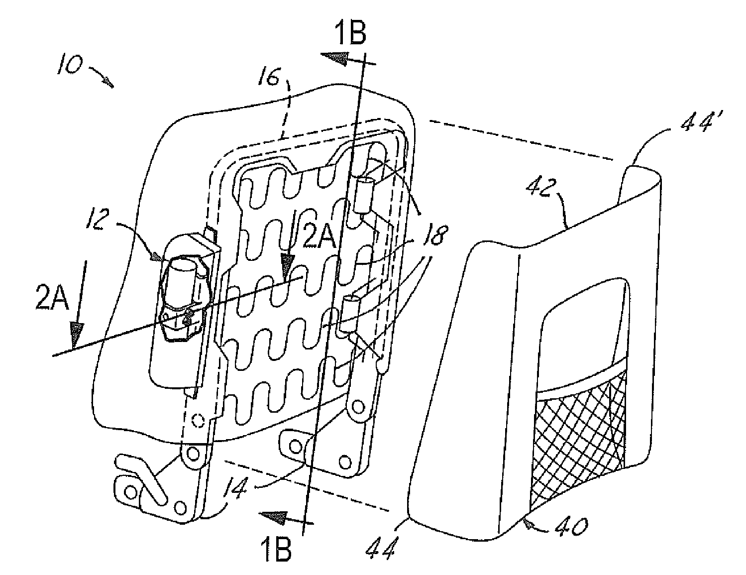
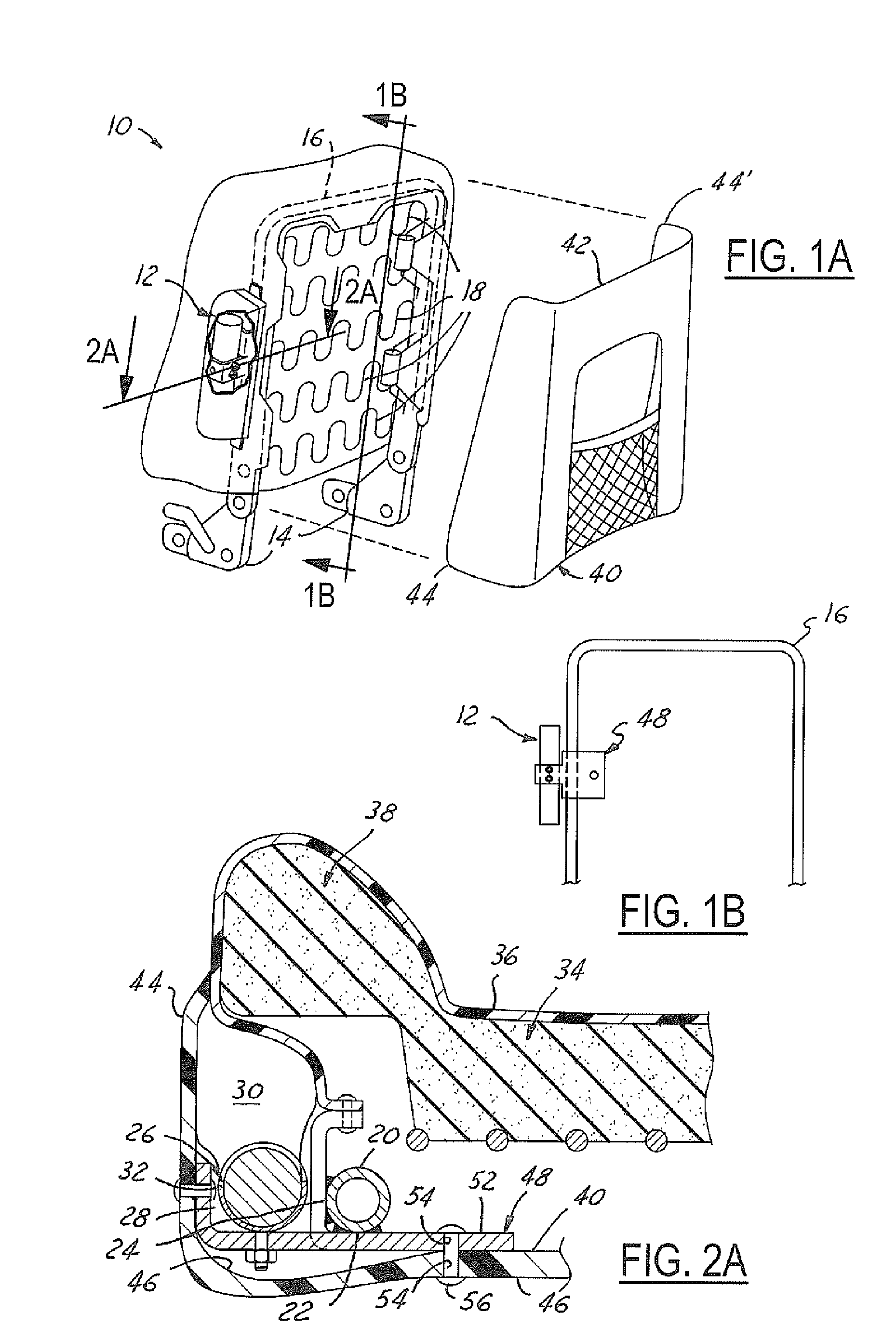
[0023]Referring to FIGS. 1A and 1B, there is shown a seatback 10 for a vehicle seat with an improved side airbag system 12 (“system”) mounted thereon, in accordance with one advantageous embodiment of the claimed invention...


PUM


Abstract

A side airbag system (12) for a vehicle is provided. The side airbag system (12) includes a seatback frame (16) having a front side (20), a rear side (22), and an outboard side (24). The outboard side (24) of the seatback frame (16) has an airbag module (26) coupled thereto and extending substantially outboard from the seatback frame (16). The airbag module (26) is positioned for deploying an airbag (30) substantially forward. The rear side (22) of the seatback frame (10) has a rear cover panel (40) attached thereon. This rear cover panel (40) is a one-piece element for covering the airbag module (26) and both the rear side (22) and the outboard side (24) of the seatback frame (16). The system (12) also includes foam cushion padding (34), which is deformed by the airbag (30) upon its deployment.

Description

TECHNICAL FIELD[0001]The present invention relates generally to supplemental restraint systems of vehicles, and more particularly to an improved side airbag system that can deploy an airbag in a substantially forward direction utilizing sufficiently few parts for decreasing manufacturing time, material costs, and various other costs associated therewith.BACKGROUND[0002]Side airbag systems for automotive vehicles are well known. Current side airbag systems typically include an airbag module mounted to a seatback frame. Usually, both the airbag module and the seatback frame are at least partially surrounded by foam cushion and one or more panels of seatback trim, which lines the foam cushion. The seatback trim can be stitched with a rip seam for easily tearing and allowing the airbag to deploy therethrough. Other side airbag systems utilize a door for deploying the airbag therethrough instead of the rip seam.[0003]Optimal deployment of side airbags through rip seams typically requires...

Claims


Application Information

Patent Timeline
Patent Type & Authority Patents(United States)
IPC IPC(8): B60R21/207
CPCB60R21/207B60N2/5816B60N2/6009B60R2021/21512B60N2002/5808
Inventor ABRAMCZYK, JOSEPH E.EWING, KURT L.MEZZADRI, ROBERT J.FRUSTI, LEGAL REPRESENTATIVE, LANESEFRUSTI, THOMAS M.
Owner FORD GLOBAL TECH LLC
Why Eureka
Try Eureka