Magnetic head slider testing apparatus and magnetic head slider testing method

a slider testing and slider technology, applied in the direction of functional testing of recording heads, mounting heads within the housing, instruments, etc., can solve the problems of reducing the magnetic field generation efficiency of these coils, unable to perform successful testing, and likely caused shield insulation defect and electric characteristic defects, so as to and reduce the distance of air gaps.

Active Publication Date: 2008-04-08
HITACHI HIGH-TECH CORP
View PDF6 Cites 15 Cited by
  • Summary
  • Abstract
  • Description
  • Claims
  • Application Information

AI Technical Summary

Benefits of technology

[0015]An object of the present invention is to resolve the above mentioned conventional problems and to provide a magnetic head slider test apparatus which permits to share in common a current output circuit for DC magnetic field and for high frequency magnetic field and to suppress leakage magnetic field from such as a core and a coil to the surroundings.

Problems solved by technology

Different from the inductive head at a write side, in the MR head defects such as resistance defect, insulation defect between shields and electric characteristic defect are likely caused.
During testing of the head slider (under slider single body condition), if the connection terminals of four or six are not surely contacted with a probe, the testing cannot be performed successfully.
However, since the test area where the connection terminals of the head slider contact with the probe is limited to one portion, only a single core having an air gap in which magnetic field is generated can be provided therein.
The magnetic field generation efficiency of these coils reduces as the position thereof on the core is separated from the test area.
Therefore, if the inductance thereof is not increased, a magnetic field having a desired intensity cannot be generated at the test area (air gap).
When a rectangular frame shaped core is used, in these sorts of magnetic head slider test apparatus, it is difficult to provide two series of coils for the DC magnetic field generation and for the high frequency magnetic field generation on one side having the air gap because of the layout such as of a test stage and test probe provided around the test area.
In this instance, since the position of the coils are remote from the air gap (test area), the inductance (number of their turns) of the coils increases, and an increase of the leakage magnetic field to the surroundings cannot be avoided, which adversely affects the test result and in addition causes a problem of increasing the entire size of the apparatus.

Method used


Image

  • Magnetic head slider testing apparatus and magnetic head slider testing method
  • Magnetic head slider testing apparatus and magnetic head slider testing method
  • Magnetic head slider testing apparatus and magnetic head slider testing method

Examples


Embodiment Construction

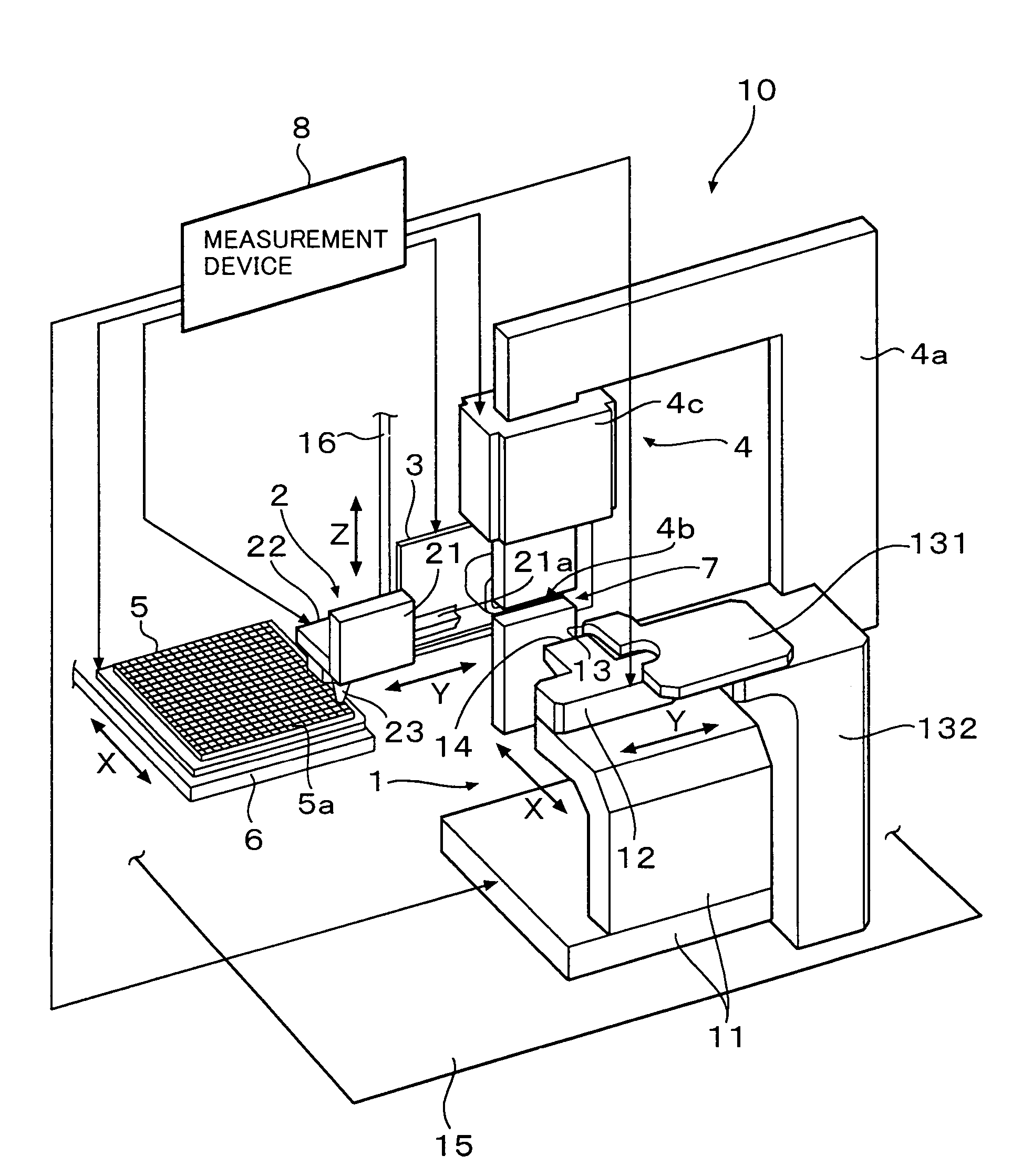
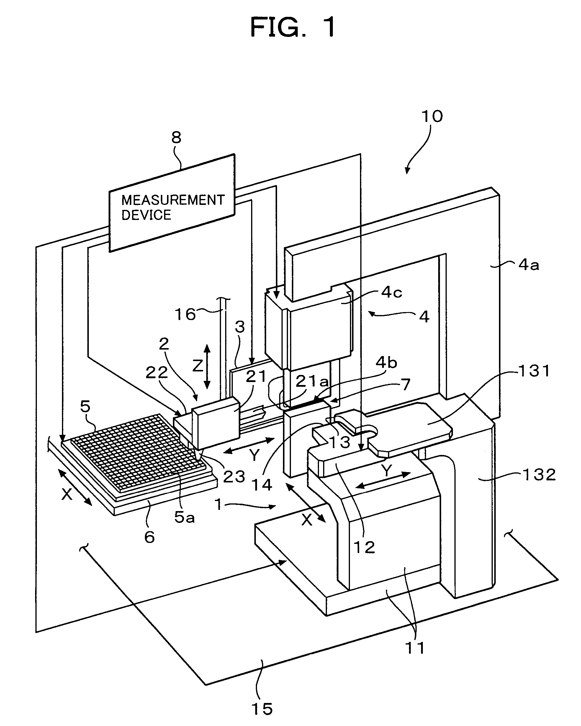
[0033]10 is a magnetic field head slider testing apparatus, wherein 1 is a testing stage, 2 a handling robot, 3 a testing probe unit, 4 an external magnetic field generating device, 5 a pallet (see FIG. 3), 6 a pallet moving stage, 7 a measurement portion, 8 a measurement device and 9 a head slider (herein after will be called as slider and see FIGS. 3 and 4). The pallet 5 stores sliders 9 in many storage holes 5a aligned in length and breadth directions.

[0034]The testing stage 1 is an XY moving stage and is constituted by an X stage 11, a Y stage 12 provided on the X stage 11, a side face butt-positioning portion 13 provided at the upper portion over the Y stage 12 (see FIG. 5) and a back face butt-positioning portion 14 provided ajacent to the Y stage 12.

[0035]The side face butt-positioning portion 13 and the back face butt-positioning portion 14 respectively comprise contacting side faces to which the side face of the slider 9 and the leading edge (the back face with respect to t...


PUM


Abstract

In the present invention, a coil generating DC magnetic field applied to a magnetic head is divided into two in that a first coil and a second coil, which are provided on a frame shape core. An distance of an air gap is shortened, a slider head is held on a table having a top end portion of thin thickness, while advancing and retreating the table in the direction perpendicular to the core, the head slider is inserted into the air gap from the lateral direction. Thereby, the distance of the air gap is reduced to about half of the conventional one and a reduction of inductance of the first coil and the second coil is realized.

Description

FIELD OF THE INVENTION[0001]The present invention relates to a magnetic head slider testing apparatus and magnetic head slider testing method, and more specifically, in a testing apparatus of a complex magnetic head having an MR (Magneto Resistive) head, in particular in a magnetic head slider testing apparatus which measures electrical characteristics of the MR head under a slider single body (chip) condition, relates to an improvement in a magnetic head slider testing apparatus, which permits to share in common a current output circuit for DC magnetic field and for high frequency magnetic field and to suppress leakage magnetic field from such as a core and a coil to the surroundings, thereby, realizes size reduction of the apparatus.[0002]High frequency referred to in the present specification and in the appended claims does not imply a frequency of more than 3 MHz used in a radio field, but implies a high frequency with respect to a commercial power source frequency of 100 Hz˜200...

Claims


Application Information

Patent Timeline
Patent Type & Authority Patents(United States)
IPC IPC(8): G01R33/12
CPCG11B5/10G11B5/102G11B5/105G11B5/3173G11B5/3189G11B5/455G11B5/4555G11B5/3166G11B2005/0016G11B5/012G11B2005/3996
Inventor TOKUTOMI, TERUAKIMORI, KYOICHI
Owner HITACHI HIGH-TECH CORP
Why Eureka
Try Eureka