Rotary type electric shaver

a rotary type, electric shaver technology, applied in the direction of rod connections, fastening means, metal working apparatuses, etc., can solve the problem that the shaver cannot provide sharp and clean shaving, and achieve the effect of preventing excessive shaving, smooth cutting of hair, and improving cutting feeling

Inactive Publication Date: 2008-04-15
IZUMI PROD CO
View PDF13 Cites 13 Cited by
  • Summary
  • Abstract
  • Description
  • Claims
  • Application Information

AI Technical Summary

Benefits of technology

[0009]It is, therefore, a first object of the present invention to provide a rotary type electric that provides sharp and clean shaving of hair.
[0010]It is a second object of the present invention to provide a method for manufacturing an outer cutter that contributes to the shaver's sharp and clean shaving capabilities.
[0014]In the structure of the present invention, as seen from the above, the cutting edge angle, which is formed by the inner cutter rotational direction at the lower end of the side wall surface of the hair introduction opening on the forefront side of the inner cutter rotational direction, is an acute angle in cross section substantially orthogonal to the length of the hair introduction opening of the outer cutter. As a result, hair that enters the hair introduction opening is pinched by the outer cutter's cutting edge, which is at the lower end of the side wall surface of the hair introduction opening and on the forefront side in the inner cutter rotational direction, and by the cutting edge of the inner cutter, and is cut. Since the cutting edge of the outer cutter has an acute angle, the hair is cut into from both sides by the acute angle cutting edge of the outer cutter and by the acute angle cutting edge of the inner cutter. As a result, the hair is cut smoothly and in good order with an improved cutting feeling.
[0015]In the present invention, the acute angle is formed on the cutting edge of only one side wall surface of the hair introduction opening of the outer cutter that is on the forefront side in the inner cutter rotational direction. In this structure, the two opposing side wall surfaces of the hair introduction opening can be made parallel planes in a slanted manner so that their lower ends are displaced into the direction opposite to the inner cutter rotating direction. In this structure, skin pressed against the shaving surface touches the slanted side wall surface and has difficulty entering deeply into the hair introduction opening, and excessively deep shaving can be prevented. This type of hair introduction openings can be obtained by bringing a thin disk-shaped rotary cutting blade with substantially the same thickness as the width of the hair introduction opening into contact with the thin layer portion in a slanted manner at an angle that is not a right angle.
[0016]In the present invention, the cutting edges at the lower ends of two opposing wall surfaces of the hair introduction openings that are defined by the neighboring ribs can take acute angles on the forefront side of the inner cutter rotational direction and on the rearward side of the inner cutter rotational direction (or on the opposite side to the inner cutter rotational direction). With this structure, ribs that make two adjacent hair introduction openings are increased in strength. In other word, since the acute-angle cutting edges project along the both lower ends of the side wall surfaces of each one of the ribs, the rigidity of the ribs increase, and it is less likely that the ribs vibrate in the inner cutter rotational direction.
[0018]Furthermore, since each hair introduction opening is wide at the top and narrow at the bottom due to the opposing projected cutting edges, skin can easily enter the hair introduction opening; and thus, it is possible to shave with appropriate depth even when the thin layer portion is thick. An outer cutter having this structure in which the opposing cutting edges project out at the lower ends of each one of the ribs can be obtained by etching, for instance, or deformation processing such as pressing. If pressing is employed, the mold that processes the rib is provided with chamfer parts that correspond to the acute cutting edge.

Problems solved by technology

As a result, the shaver cannot provide sharp and clean shaving.

Method used


Image

  • Rotary type electric shaver
  • Rotary type electric shaver
  • Rotary type electric shaver

Examples


Embodiment Construction

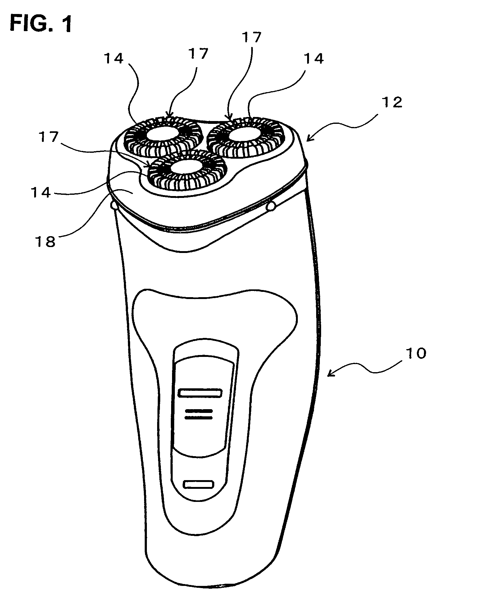
[0026]In FIG. 1, the reference numeral 10 is a shaver main body, and 12 is the cutter head openably or detachably attached to the upper part thereof. Three cutter units 17 each formed by an outer cutter 14 and an inner cutter 16 and so forth are installed in the cutter head 12. The outer cutters 14 corresponding to the three cutter units 17 are positioned with their centers at the vertices of an equilateral triangle.

[0027]The cutter head 12 has an outer cutter frame 18 (FIG. 1) that is openable or detachable upward relative to the shaver main body 10. The outer cutters 14 are installed in three outer cutter installation holes formed in the outer cutter frame 18. The cutter unit 17 that includes the outer cutter 14 is urged upward or in such a direction that the outer cutter 14 projects upward.

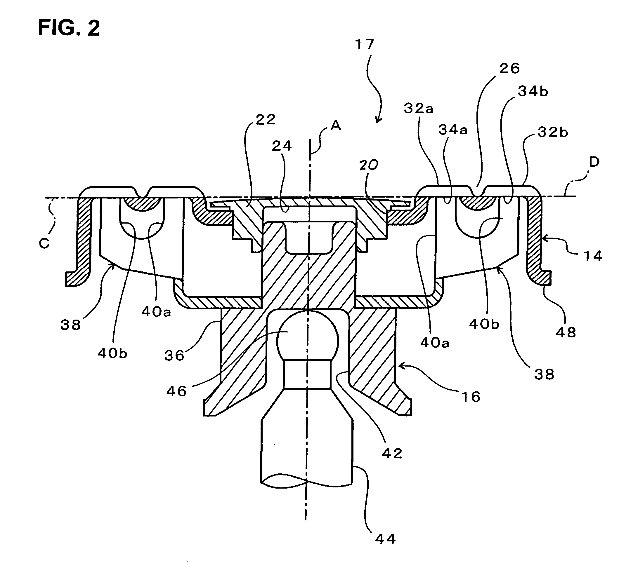
[0028]The outer cutter 14 is made of metal in which a metal plate is formed into a substantially shallow bowl shape that is convex upward (see FIGS. 2 and 3). The upper part of the outer cutter...


PUM


Abstract

A rotary shaver including an outer cutter frame (18) provided on a shaver main body (10), an outer cutter (14) that is installed in this outer cutter frame (18) and has ring-shaped thin layer portions (28a, 28b) whose upper surfaces are the shaving surfaces, and an inner cutter (16) that has cutter bodies (38) that rotates and make sliding contact with the lower surface of the thin layer portions of the outer cutter to cut hair that entered hair introduction openings (30a, 30b) formed in the thin layer portions; wherein the hair introduction openings have a slit shape extending in substantially the radial direction of the thin layer portions, and the cutting edge angle (p, q) at the lower end(s) of the side wall surface(s) of the hair introduction openings (30a, 30b) defined by the ribs (32a, 32b) is an acute angle.

Description

BACKGROUND OF THE INVENTION[0001]1. Field of the Invention[0002]The present invention relates to a rotary type electric shaver including an outer cutter(s) having a shaving surface on an upper surface of a ring-shaped thin layer portion thereof and an inner cutter(s) rotationally making sliding contact from below with the lower surface of the thin layer portion of the outer cutter(s), thus cutting whiskers (hair) advancing into a hair introduction opening formed in the thin layer portion.[0003]2. Description of the Related Art[0004]In an electric shaver of the type as described above, hair introduction openings are formed so as to transect the thin layer portion of an outer cutter in substantially the radial direction, and the hair introduction openings are formed in a slit shape of substantially constant width. Each hair introduction opening (“slit”) conventionally has side wall surfaces that are perpendicular to the upper surface of the thin layer portion of the outer cutter in cr...

Claims


Application Information

Patent Timeline
Patent Type & Authority Patents(United States)
IPC IPC(8): B26B19/16
CPCB26B19/141B26B19/143B26B19/3846F16B7/04
Inventor NAKANO, TSUYOSHI
Owner IZUMI PROD CO
Why Eureka
Try Eureka