Electrical connector within tubular structure

a technology of electrical connectors and tubular structures, applied in the direction of connection contact material, coupling device connection, lighting and heating apparatus, etc., can solve the problem of difficult coupling of electrical wiring in these tubular structures

Inactive Publication Date: 2008-04-22
HUNTER FAN
View PDF4 Cites 34 Cited by
  • Summary
  • Abstract
  • Description
  • Claims
  • Application Information

AI Technical Summary

Problems solved by technology

It is often difficult to couple the electrical wiring for these tubular structures because of the length of the elongated pole.

Method used


Image

  • Electrical connector within tubular structure
  • Electrical connector within tubular structure
  • Electrical connector within tubular structure

Examples


Embodiment Construction

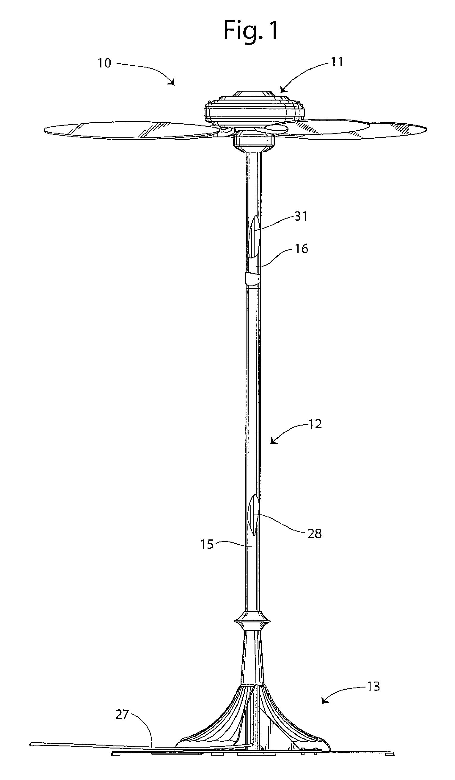
[0008]FIG. 1 illustrates an electrical connector with tubular structure in the form of a pole fan 10. The pole fan 10 includes a generally conventional ceiling fan motor assembly 11 mounted to the top end of an elongated tubular pole 12 opposite a pedestal base 13.

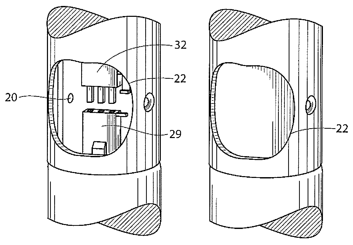
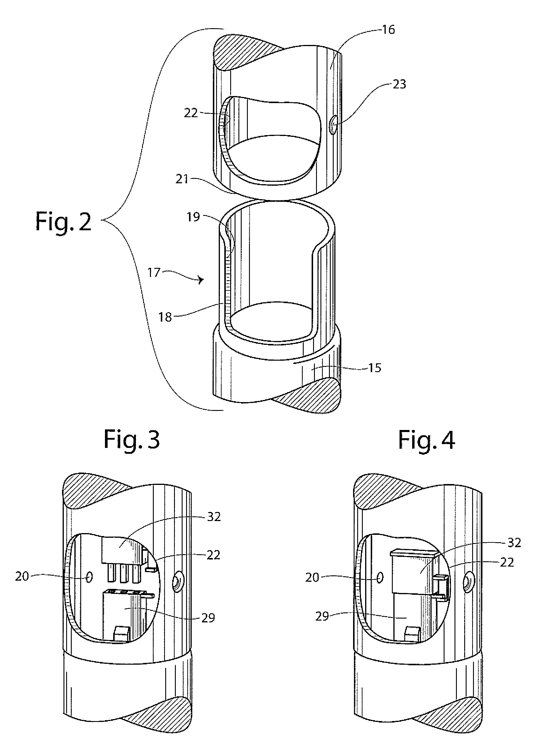
[0009]The pole 12 includes a tubular bottom portion 15 and a tubular top portion 16. As best shown in FIG. 2, the bottom portion 16 has a top connecting end 17 having a narrowed neck 18 with a large notch 19 therein extending from the top end 17 and two threaded screw mounting holes 20. The pole top portion 16 has a bottom connecting end 21 having an internal diameter sized to receive the neck 18 of the bottom portion. The pole top portion 16 also has a window 22 therein and a pair of screw holes 23 on either side of the window 22. A cover plate 24 is configured to be mounted over the window 22. The cover plate 24 has a pair of oppositely disposed screw holes 25 configured to allow the passage of mounting screws 26 which a...


PUM


Abstract

An electrical connector within a tubular structure is disclosed which includes a pole (12) having a tubular bottom portion (15) and a tubular top portion (16). The bottom portion has a top connecting end (17) having a narrowed neck (18) with a large notch (19). The pole top portion has a bottom connecting end (21) having an internal diameter sized to receive the neck of the bottom portion. The pole top portion also has a window (22) therein. A cover plate (24) is configured to be mounted over the window. The structure also includes an electrical cord (27) which provides an electrical current to a device coupled to the pole. The electrical cord has a first portion (28) terminating with a female electrical coupler or connector (29) and a second portion terminating with a male electrical coupler (32). The male coupler or connector is configured to be received within the female coupler.

Description

REFERENCE TO RELATED APPLICATION[0001]The application claims benefit of provisional patent application Ser. No. 60 / 814,671 filed Jun. 16, 2006.TECHNICAL FIELD[0002]This invention relates generally to electrical connectors, and specifically to electrical connectors positioned within elongated tubular structures.BACKGROUND OF THE INVENTION[0003]Tubular structures oftentimes includes electrical wiring therethrough, such as fans mounted to the top end of an elongated pole have existed. It is often difficult to couple the electrical wiring for these tubular structures because of the length of the elongated pole.[0004]Accordingly, it is seen that a need remains for a connector which enables one to easily connect electrical wiring within an elongated tubular structure. It is to the provision of such therefore that the present invention is primarily directed.SUMMARY OF THE INVENTION[0005]A tubular structure and electrical connector comprises a tubular pole having a first pole portion and a ...

Claims


Application Information

Patent Timeline
Patent Type & Authority Patents(United States)
IPC IPC(8): H01R4/60
CPCH01R13/629Y10S439/91
Inventor KOEHLER, EDWIN T.
Owner HUNTER FAN
Why Eureka
Try Eureka