Cable reel

a cable reel and cable technology, applied in the field of cable reels, can solve the problems of easy falling off of the ball bearing, inconvenient use, and difficult control of the roll direction and position, and achieve the effect of convenient cable storage and simple us

Inactive Publication Date: 2008-04-29
FIRST CLASS ELECTRICAL
View PDF8 Cites 58 Cited by
  • Summary
  • Abstract
  • Description
  • Claims
  • Application Information

AI Technical Summary

Benefits of technology

[0007]It is therefore the primary objective of the present invention to provide a cable reel, which comprises a casing, a turntable pivotally coupled to the casing, a volute spring disposed in the turntable, a cable wound around the turntable, and an adapter connectable to one end or both ends of the cable. Further, the turntable comprises a groove, a latch member disposed in the groove and one end of the latch member being pivotally coupled to the casing, and an inclined groove and an arc indented groove being disposed proximate to the groove, so that the movement of the latch member in conjunction with the inclined groove and the arc indented groove pulls the cable out to a certain specific length and produces a latch effect on stopping the cable from retrogressing at various different stages and fixing the cable at the currently located position. On the other hand, the cable can be pulled further to release the latch effect, so that the cable will be rewound automatically. Such arrangement not only is simple to use, but also is very convenient for storing the cable.
[0009]To make it easier for our examiner to understand the objective of the invention, its structure, innovative features, and performance, we use a preferred embodiment including but not limited to the attached drawings for the detailed description of the invention.

Problems solved by technology

However, it is necessary to open the lid first before using the cable coiler, and the periphery of the cable axle is flat and straight and has no device for stopping the coil.
Furthermore, the length of the cable extended from the cable coiler cannot be pulled according to the user's requirement and the cable cannot be fixed at the currently located position, which is very inconvenient for its use.
Although the structure of this device can prevent rewinding the cable, yet the ball bearing is a spherical object which is not easy to control its rolling direction and position, even if there is a stop groove to limit the scope of its rolling.
Further, the ball bearing will fall off from the stop groove easily when the casing is disassembled and opened, and users may have difficulties to find the missing ball bearing.

Method used


Image

  • Cable reel
  • Cable reel
  • Cable reel

Examples


Embodiment Construction

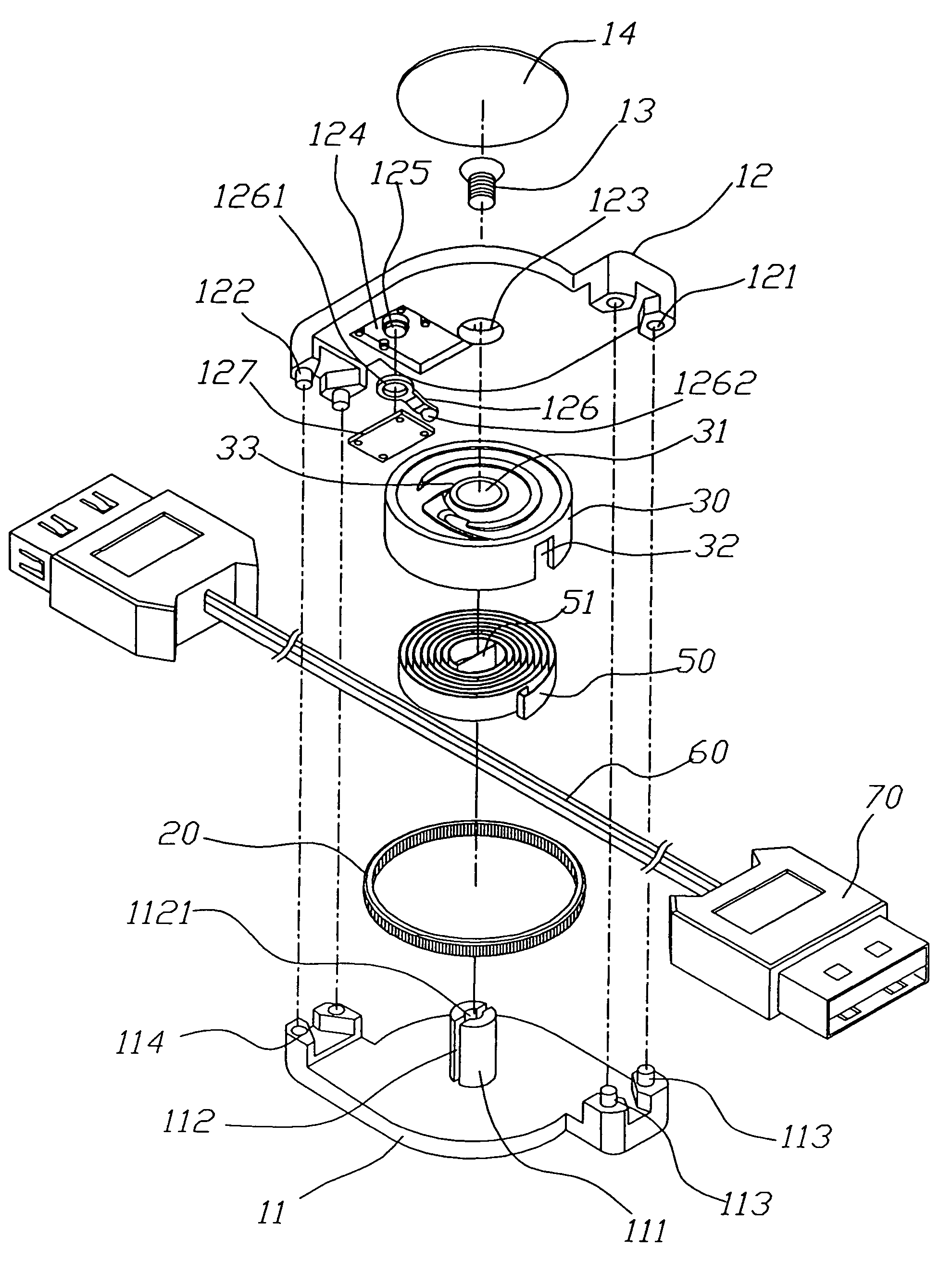
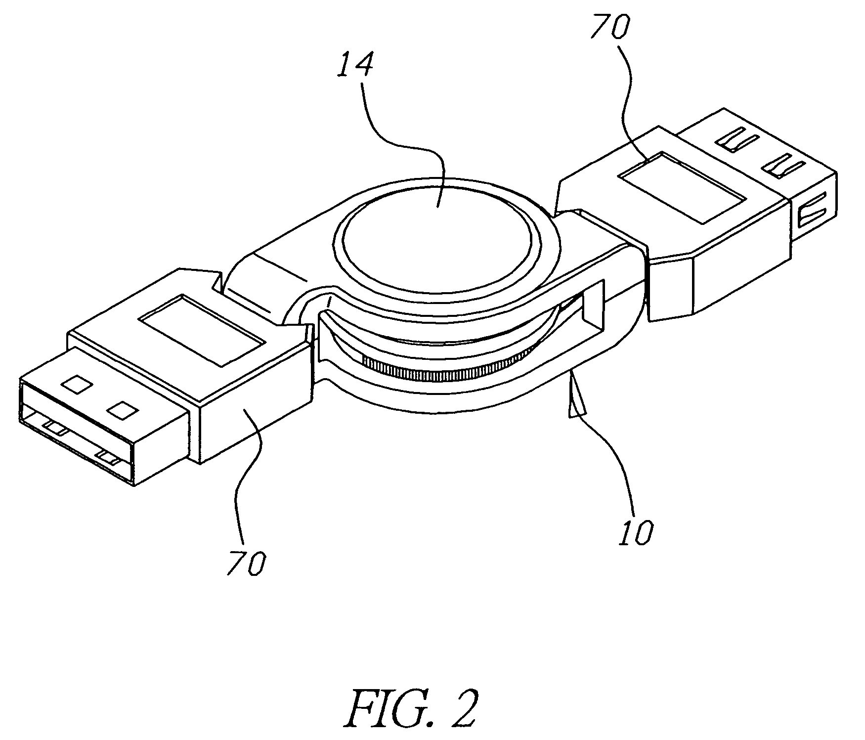
[0021]Please refer to FIGS. 2 and 3 for the cable reel according to a preferred embodiment of the present invention. The cable reel comprises a casing 10, and the casing 10 comprises a first external casing 11 and a second external casing 12, wherein an axle pole 111 is protruded outward from one side of the first external casing 11, and the axle pole 111 has an open groove 112 extending along the axial direction and passing through the axle pole 111, and the open groove 112 has a screw hole 1121, and a protruded pole 113 and a groove 114 are disposed on both sides of the first external casing 11. Further, the second external casing 12 comprises a protruded pole 122 and a groove 121 disposed on both sides corresponding to the protruded pole 113 and the groove 114, so that the second external casing 12 is coupled with the first external casing 11 by latching the groove 121 and protruded pole 113 and the protruded pole 122 and the groove 114 respectively.

[0022]Further, the second exte...


PUM


Abstract

The present invention discloses a cable reel, which comprises a casing, a movable latch member pivotally coupled into the casing, a protrusion disposed at one end of the latch member, a turntable disposed under the latch member and pivotally coupled into the casing, a volute spring disposed on a turntable, a cable disposed in the in the turntable, and an adapter can be connected to one end or both ends of the cable. Further, the turntable has a groove, and an inclined guide groove and an arc indented groove are disposed proximate to the groove such that the protrusion on the latch member in conjunction with the inclined guide groove and the arc indented groove can fix the cable at the currently located position and will not retract the cable into the cable reel when the cable is pulled. On the other hand, the cable is pulled gently again if it is necessary to rewind the cable. The protrusion of the latch member will then be released and the cable around the turntable will be retracted automatically to the turntable. The present invention not only is simple to use, but also is easy to carry.

Description

BACKGROUND OF THE INVENTION[0001]1. Field of the Invention[0002]The present invention relates to a cable reel, more particularly to a cable reel assembly comprising a latch member, an inclined guide groove and an indented groove, such that the cable can be pulled to extend to a desired length and fixed temporarily at such position or the cable is pulled again to rewind the cable into the cable reel.[0003]2. Description of the Related Art[0004]In general, a cable coiler comes with a box member, and the box member has a rotary cable axle, and a transparent lid covers the top of the box member. Although the rotary axle of the cable coiler can be rotated to continuously coil the cable onto the cable axle for winding the cable. However, it is necessary to open the lid first before using the cable coiler, and the periphery of the cable axle is flat and straight and has no device for stopping the coil. If the number of coils of the cable is too large, then the cable will come off from the ...

Claims


Application Information

Patent Timeline
Patent Type & Authority Patents(United States)
IPC IPC(8): B65H75/48
CPCB65H75/4434H02G11/02
Inventor KUO, CHIN-CHANG
Owner FIRST CLASS ELECTRICAL
Why Eureka
Try Eureka