Clamping device for a sewing machine and method

a technology for sewing machines and hooping devices, which is applied in the direction of sewing machine components, take-up devices, automatic machines, etc., can solve the problems of inability to accept stitching or embroidering patterns, awkward prior hooping devices in certain respects, and difficulty in loading, adjusting and unloading, etc., and achieves relative ease of adjustment vertically and horizontally.

Active Publication Date: 2008-05-27
EFP INC
View PDF12 Cites 20 Cited by
  • Summary
  • Abstract
  • Description
  • Claims
  • Application Information

AI Technical Summary

Benefits of technology

[0011]The aforesaid and other objectives are realized by providing a material clamping device and method of use which assures speed and efficiency during the installation and stitching or embroidering process. The clamping device includes a pair of arms extend from the sewing machine towards the operator proximate the sewing head. Each of the arms include a fixed and a vertically movable section whereby a finger lever affixed to a cam raises and lowers the movable arm section to release or clamp selected material therebetween. Each of the arms also include a bracket for affixing the arm to a mounting plate attached to the sewing machine at the sewing head. Allen head screws in the bracket allow the arm to adjust vertically and a threaded member with a knob allows each of the arms to be spatially aligned, one to the other as they move horizontally along the mounting plate. In use the levers are raised thereby opening the movable section of the arms for engagement with a material such as a shirt fabric or the like. Once the arms engage the material the levers are closed to provide a tightening effect to the fabric. The sewing head is then utilized to embroider or stitch on the tightened material. Once the pattern or design is embroidered completely the levers can be lifted, the material removed from the clamping device and another type or thickness of material can be inserted and tightened for sewing without horizontal movement of the arms.

Problems solved by technology

Wrinkles, gaps or loose material will often create an unacceptable stitching or embroidering pattern and the embroidered item such as a shirt, cap, uniform or the like will have to be reprocessed again or discarded.
The prior hooping devices were awkward in certain respects and were often difficult to load, adjust and unload after the stitching / embroidering process was complete.

Method used


Image

  • Clamping device for a sewing machine and method
  • Clamping device for a sewing machine and method
  • Clamping device for a sewing machine and method

Examples


Embodiment Construction

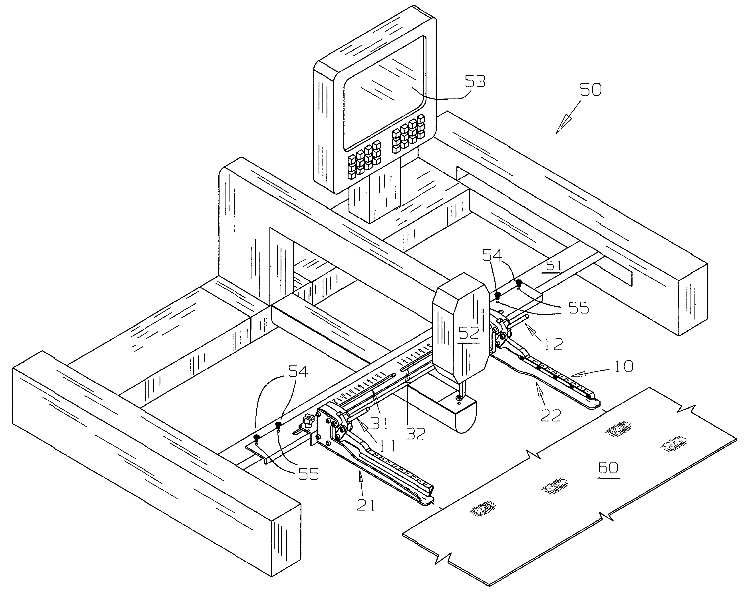
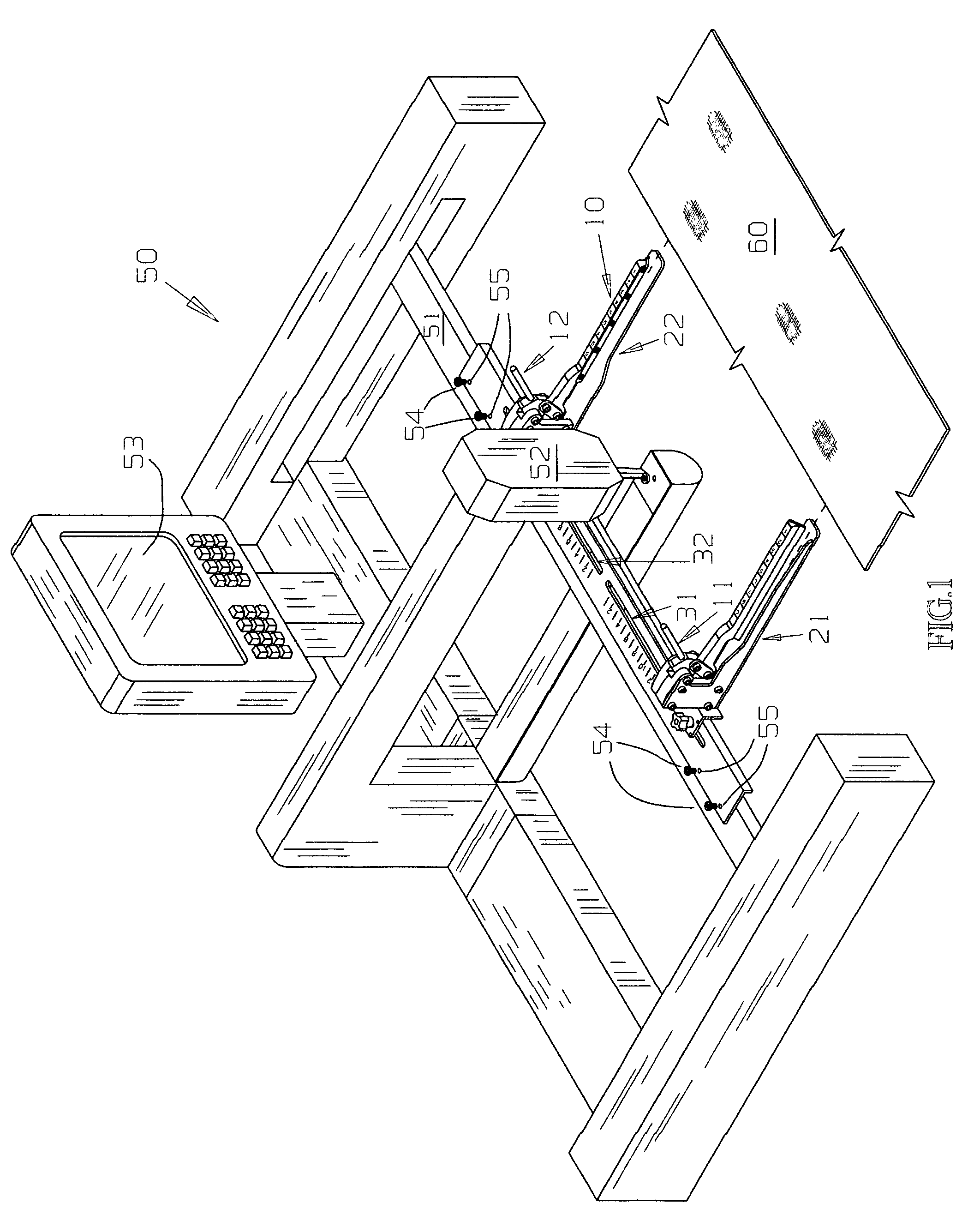
[0022]For a better understanding of the invention and its operation, turning now to the drawings. FIG. 1 illustrates preferred clamping device 10 formed from steel or other suitable material attached to frame member 51 of sewing machine 50. Sewing machine 50 is a typical head embroidery machine having sewing head 52 with a single needle (not shown) for embroidering, stitching or sewing materials such as caps, jackets, shirts or the like. Conventional control panel 53 allows the operator to program and / or direct X-Y movements of frame member 51 and sewing head 52 as required during the stitching or embroidering process.

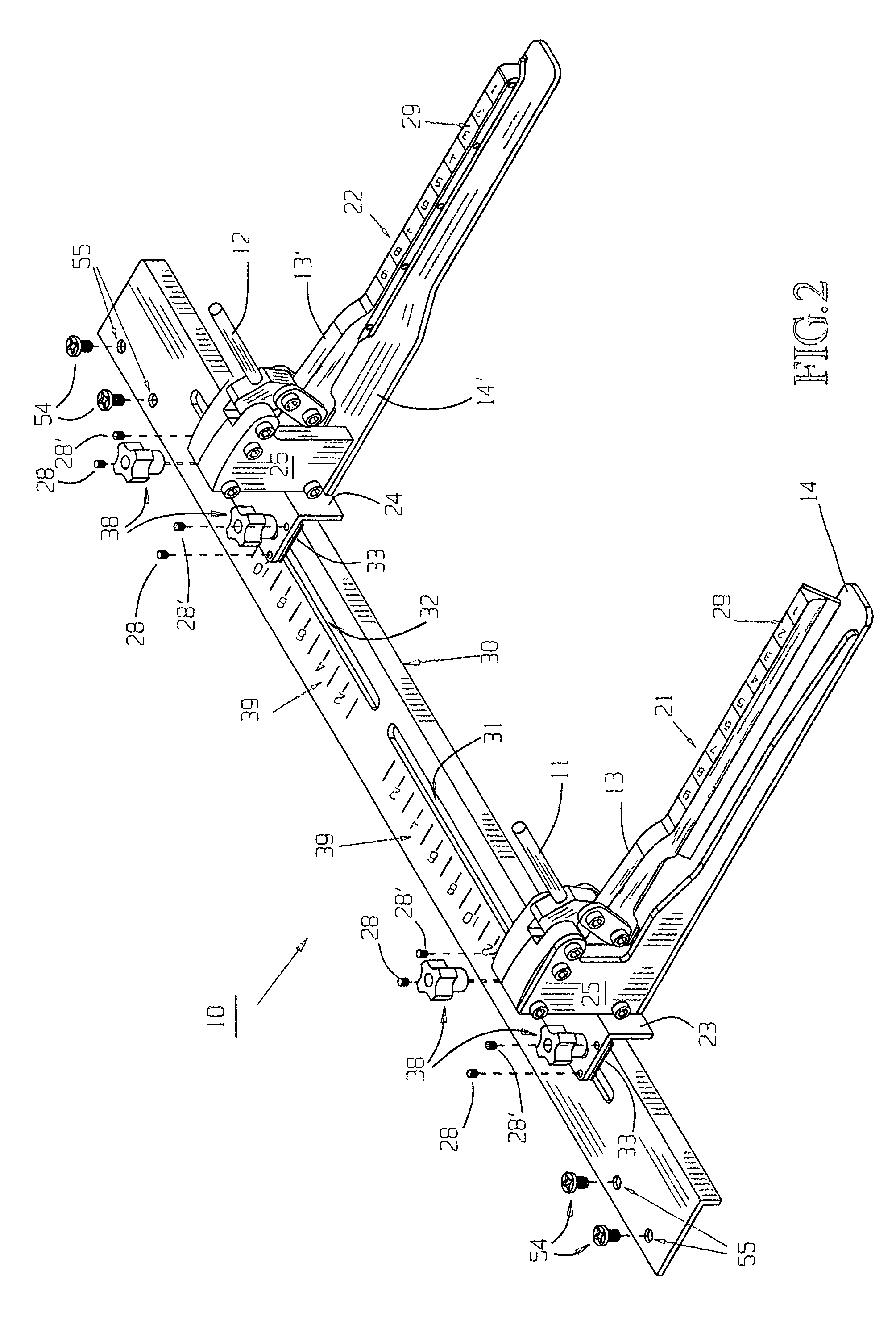
[0023]Clamping device 10 is affixed to X-Y frame member 51 by bolts 52. Bolts 54 pass through apertures 55 in L-shaped mounting plate 30 seen enlarged in FIG. 2. Mounting plate 30 includes slots 31, 32 which allows arms 21, 22 to slide therealong for adjusting the space between arms 21 and 22 as required, depending on the size of the selected item and the pattern to be...


PUM

PropertyMeasurementUnit
anglesaaaaaaaaaa
resilientaaaaaaaaaa
flexibleaaaaaaaaaa

Abstract

A clamping device and method for a conventional sewing or embroidery machine has a pair of movable arms. Each of the arms includes a fixed section and a movable section for receiving material or item to be embroidered therebetween. A manual lever allows the movable arm to be raised for insertion of the material and a scale on the arm allows the depth of insertion to be easily determined for accurate insertion. Each arm is movable along a slotted mounting plate affixed to the sewing machine proximate the sewing head. The clamping device provides uniform, taut material for accurate, smooth embroidering.

Description

FIELD OF THE INVENTION[0001]The invention herein pertains to clamping devices for sewing machines and particularly pertains to a clamping device for use on a typical embroidering machine.DESCRIPTION OF THE PRIOR ART AND OBJECTIVES OF THE INVENTION[0002]During the process of stitching or embroidering on fabrics and other materials, such materials must be held or contained in a taut, fixed configuration to ensure the embroidery pattern is correctly applied. Wrinkles, gaps or loose material will often create an unacceptable stitching or embroidering pattern and the embroidered item such as a shirt, cap, uniform or the like will have to be reprocessed again or discarded.[0003]Initially hand stitching or embroidered utilized “hoops” formed from wood, metal or plastic that were used to tighten a section of, for example, fabric over a shirt pocket. Once the fabric was “hooped” the embroidery process could proceed with fairly good results. With the advent of high speed sewing machines more ...

Claims


Application Information

Patent Timeline
Patent Type & Authority Patents(United States)
IPC IPC(8): D05C9/04D05B49/00
CPCD05B35/04D05B39/00D05C9/04D05C13/02
Inventor MOORE, III, E. FRANK
Owner EFP INC
Why Eureka
Try Eureka