Magnetic disk drive

a magnetic disk and drive technology, applied in the field of magnetic disk drives, can solve the problems of low yield, difficult from the viewpoint of the fabrication process to work the head slider, and difficult to produce very fine magnetic particles, and achieve the effect of suppressing the yaw angle dependence upon recording

Inactive Publication Date: 2008-05-27
TOSHIBA STORAGE DEVICE CORP
View PDF11 Cites 10 Cited by
  • Summary
  • Abstract
  • Description
  • Claims
  • Application Information

AI Technical Summary

Benefits of technology

[0009]It is therefore an object of the present invention to provide a vertical recording magnetic disk drive which can suppresses the yaw angle dependence upon recording.

Problems solved by technology

However, according to a conventional recording method which is called in-plane recording method, since refinement of magnetic particles makes a factor of thermal instability, it is difficult to produce very fine magnetic particles.
A conventional magnetic disk drive for which a vertical recording method is used has such problems as described below.
However, it is very difficult from a viewpoint of a fabrication process to work the head slider into such a special shape as described above.
Further, also the yield is low, and a considerable expense is required from a viewpoint of the cost.

Method used


Image

  • Magnetic disk drive
  • Magnetic disk drive
  • Magnetic disk drive

Examples


first embodiment

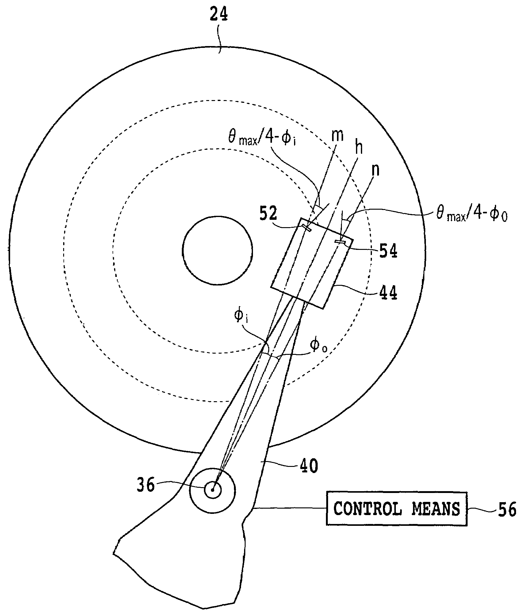
[0038]FIG. 3 shows a schematic view showing a configuration of the present invention. In FIG. 3, the suspension 46 shown in FIG. 2 is omitted, and the head slider 44 is shown carried directly at the tip end of the actuator arm 40. The head slider 44 of the present embodiment includes first and second vertical recording electromagnetic transducers 52 and 54 provided in the proximity of an air outflow end. The first electromagnetic transducer 52 is inclined in a direction in which the inner side face side thereof is nearer to the air outflow end to a central portion thereof, and the second electromagnetic transducer 54 is inclined in a direction in which the outer side face side thereof is nearer to the air outflow end than a central portion thereof.

[0039]The maximum yaw angle when the head slider 44 seeks from the innermost track to the outermost track of the magnetic disk 24 having a vertical magnetization film is represented by θmax; the angle defined by a straight line m interconn...

fifth embodiment

[0050]FIG. 9 is a schematic view showing the present invention. A head slider 44D in the present embodiment includes vertical recording electromagnetic transducers 52, 54 and 94 in the proximity of the air outflow end. In particular, the head slider 44D includes a first electromagnetic transducer 52 inclined in a direction in which the inner side face side thereof is nearer to the air outflow end than a central portion thereof, a second electromagnetic transducer 54 inclined in a direction in which the outer side face side thereof is nearer to the air outflow end than the central portion, and a third electromagnetic transducer 94 provided in the proximity of the air outflow end at a central portion in the widthwise direction.

[0051]The maximum yaw angle when the head slider 44D seeks from the innermost track to the outermost track of the magnetic disk 24 is represented by θmax; the angle defined by a straight line m interconnecting the center of pivotal motion of the actuator arm 40 ...

seventh embodiment

[0055]FIG. 11 is a schematic view showing a configuration of the present invention. A head slider 44F in the present embodiment includes three vertical recording electromagnetic transducers 86, 88 and 94 in the proximity of the air outflow end. In particular, the head slider 44F includes a first electromagnetic transducer 86 inclined in a direction in which the inner side face side thereof is farther from the air outflow end than a central portion thereof, a second electromagnetic transducer 88 inclined in a direction in which the outer side face side thereof is farther from the air outflow end than the central portion, and a third electromagnetic transducer 94 provided in the proximity of the air outflow end at a widthwise direction central portion of the head slider 44F.

[0056]The first electromagnetic transducer 86 is formed so as to be inclined by θmax / 6+φi with respect to a perpendicular line to a straight line m interconnecting the center of pivotal motion of the actuator arm 4...


PUM

PropertyMeasurementUnit
thicknessaaaaaaaaaa
thicknessaaaaaaaaaa
gap lengthaaaaaaaaaa

Abstract

A magnetic disk drive includes an actuator arm, a suspension fixed to a tip end of the actuator arm, and a head slider having at least two electromagnetic transducers mounted at a tip end of the suspension. The head slider has a first electromagnetic transducer inclined in a direction in which the inner side face side is nearer to an air outflow end than a central portion thereof, and a second electromagnetic transducer inclined in a direction in which the outer side face side is nearer to the air outflow side than the central portion thereof. A controller performs changeover control such that an inner side data region of a magnetic disk is taken charge of by the first electromagnetic transducer while an outer side data region is taken charge of by the second electromagnetic transducer.

Description

[0001]This is a continuation of PCT International Application NO. PCT / JP03 / 03176, filed Mar. 17, 2003, which was not published in English.BACKGROUND OF THE INVENTION[0002]1. Field of the Invention[0003]The present invention relates to a magnetic disk drive for vertical recording.[0004]2. Description of the Related Art[0005]In recent years, together with the progress of downsizing and increase in capacity of magnetic disk drive, refinement of magnetic particles in a medium is demanded. However, according to a conventional recording method which is called in-plane recording method, since refinement of magnetic particles makes a factor of thermal instability, it is difficult to produce very fine magnetic particles. Therefore, a vertical magnetic recording method which is superior in thermomagnetic relaxation and so forth is examined. In a common vertical magnetic recording method, a two-layer film medium is used which is formed by laminating a soft magnetic ground layer on a substrate ...

Claims


Application Information

Patent Timeline
Patent Type & Authority Patents(United States)
IPC IPC(8): G11B15/12G11B5/00G11B5/48G11B5/596G11B5/012G11B5/187G11B5/29G11B5/49G11B5/60
CPCG11B5/29G11B5/397G11B5/3977G11B5/4976G11B5/6005G11B5/3948G11B5/4886G11B5/6082
Inventor YAMAGISHI, MICHINAGA
Owner TOSHIBA STORAGE DEVICE CORP
Why Eureka
Try Eureka