Tunneling scheme optimized for use in virtual private networks

a tunneling scheme and virtual private network technology, applied in data switching networks, multiplex communication, digital transmission, etc., can solve the problems of packets missing their intended destination, high complexity of maintaining the given vpn with multiple point to point tunnels, etc., to reduce the layer 2 complexity of the carrier network

Inactive Publication Date: 2008-05-27
RPX CLEARINGHOUSE
View PDF5 Cites 93 Cited by
  • Summary
  • Abstract
  • Description
  • Claims
  • Application Information

AI Technical Summary

Benefits of technology

[0011]Advantageously, the present invention provides address separation between the end user address space and the carrier address space. Further, the present invention may reduce Layer 2 complexity in the carrier network. Even further, the present invention overcomes the problem of security threats due to configuration errors.

Problems solved by technology

Network connected devices within such a private LAN are not intended to be reachable by devices in other, unrelated networks.
Once the number of endpoints in a given VPN begins to increase, maintaining the given VPN with multiple point to point tunnels may become highly complex.
This sharing of common addresses may lead to problems when configuring multiple VPNs over a single carrier network.
In particular, a configuration error could lead to packets missing their intended destination in favor of a destination in an unrelated network.

Method used


Image

  • Tunneling scheme optimized for use in virtual private networks
  • Tunneling scheme optimized for use in virtual private networks
  • Tunneling scheme optimized for use in virtual private networks

Examples


Embodiment Construction

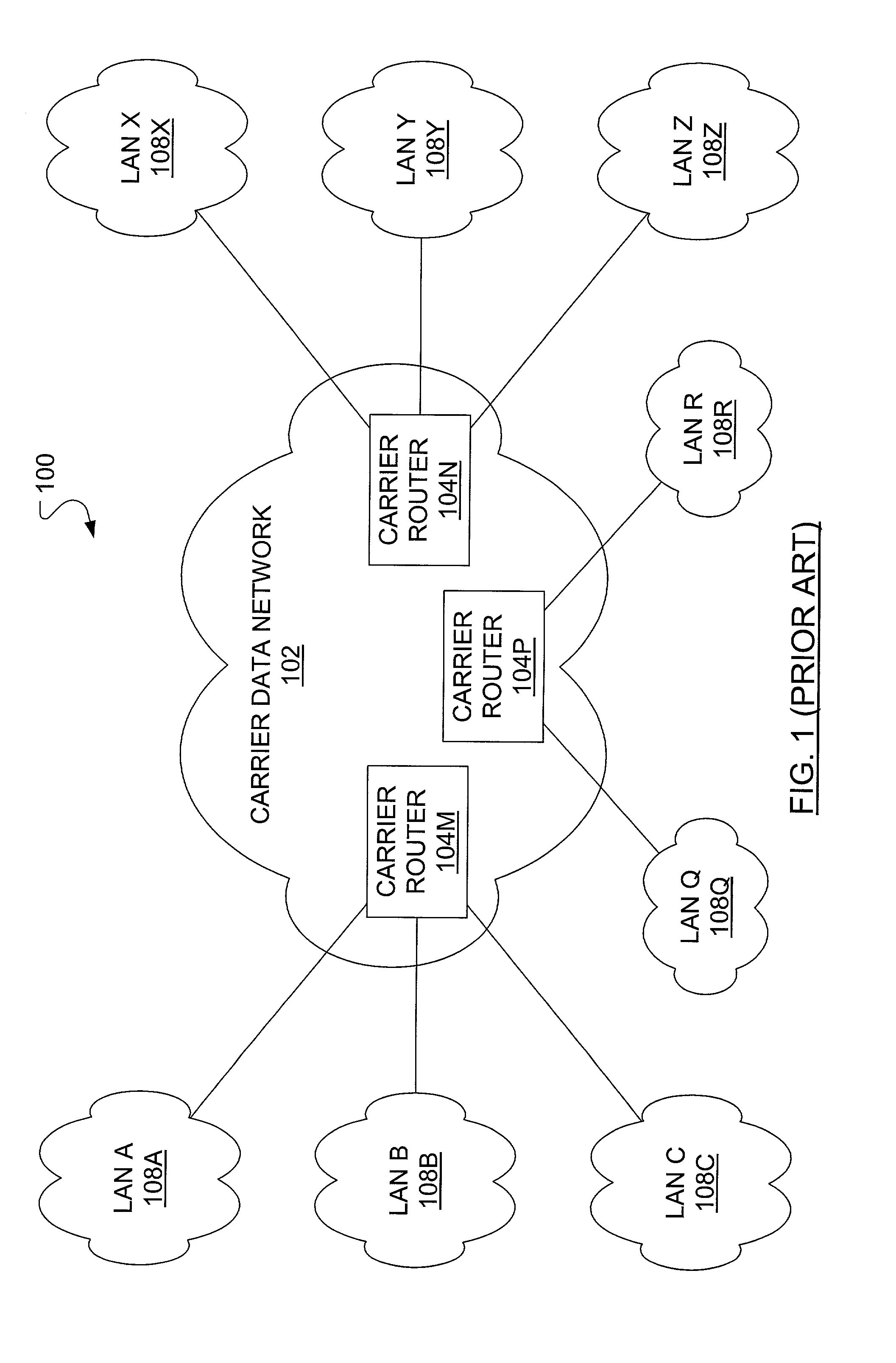
[0030]In FIG. 1, a known communication system 100 includes a carrier data network 102 in which is included a first carrier router 104M, a second carrier router 104N and a third carrier router 104P. The first carrier router 104M connects to a set of local LANs (LAN A 108A, LAN B 108B, LAN C 108C) in a respective local customer address space. The second carrier router 104N connects to a set of remote LANs (LAN X 108X, LAN Y 108Y, LAN Z 108Z) in a respective remote customer address space. The third carrier router 104P connects to a remote LAN Q 108Q and a remote LAN R 108R, each in separate customer address spaces.

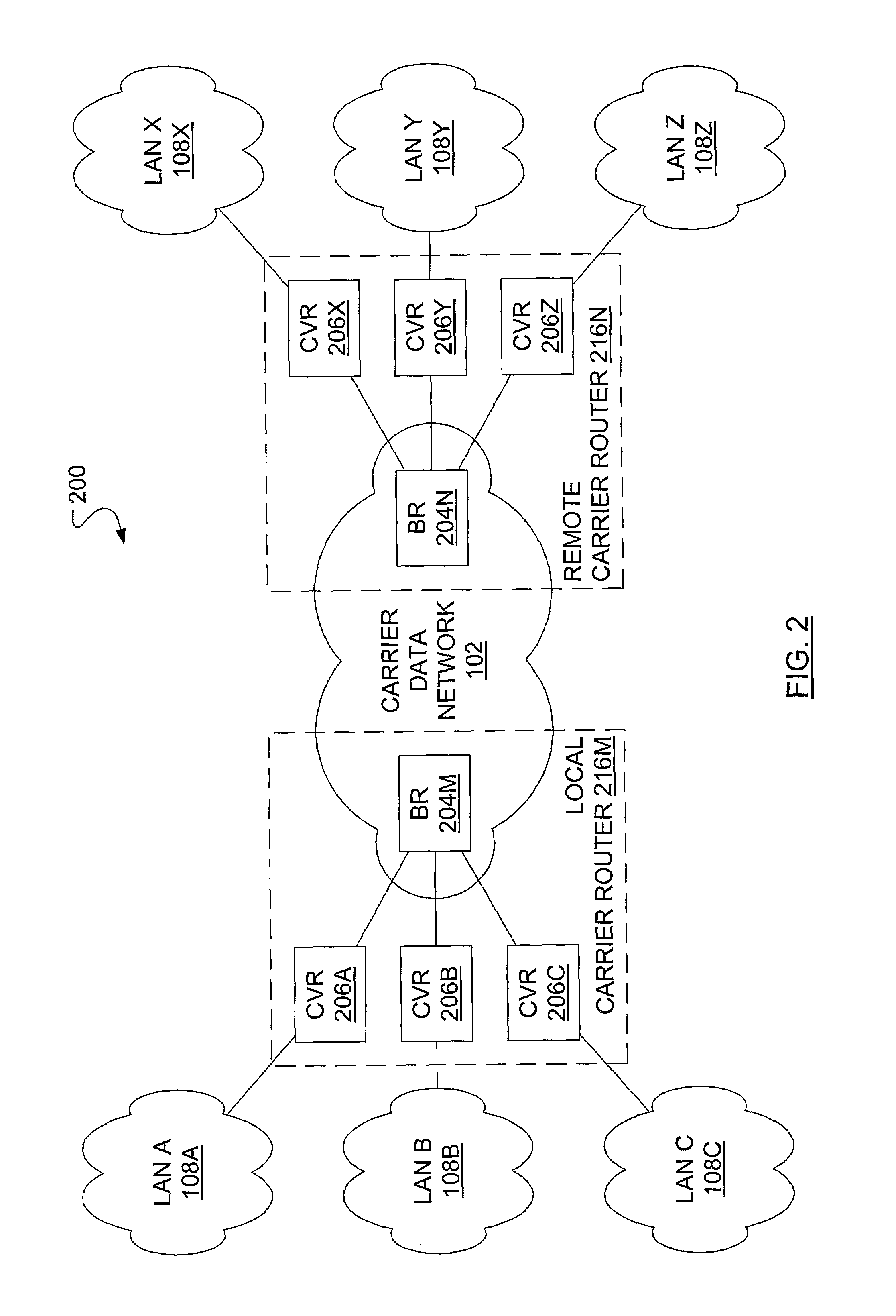
[0031]In FIG. 2, a communication system 200 includes the carrier data network 102 in which is included a local carrier router 216M and a remote carrier router 216N. The local carrier router 216M includes a local backbone router (BR) 204M and a number of local customer virtual routers 206A, 206B, 206C (referred to individually or collectively as customer virtual routers 206). ...


PUM


Abstract

A tunneling scheme includes the creation of tunnels having a source address and potentially multiple destination addresses. Each tunnel endpoint is divided into two sub-endpoints, where one sub-endpoint has a public network address and the other sub-endpoint has a private network address. Also included in the tunneling scheme is a static Address Resolution Protocol (ARP) table. The static ARP table contains information on virtual private network membership. More particularly, the static ARP table provides address resolution between public network addresses and private network addresses.

Description

FIELD OF THE INVENTION[0001]The present invention relates to virtual private networks provided within public data networks and, in particular, to a tunneling scheme optimized for use in virtual private networks.BACKGROUND OF THE INVENTION[0002]Traditionally, to securely connect geographically distributed private local area networks (LANs) of an enterprise to each other, hard-wired connections were leased from telecommunication companies, or at least an amount of guaranteed bandwidth on these connections. As well, to connect a single remote user to a private LAN, the remote user would dial in to a dedicated collection of modems, phone lines and associated network access servers. These private LANs are typically used for networking functions (e.g., e-mail, file sharing, printing) within an enterprise. Network connected devices within such a private LAN are not intended to be reachable by devices in other, unrelated networks. Increasingly, the use of Virtual Private Networks (VPNs) is ...

Claims


Application Information

Patent Timeline
Patent Type & Authority Patents(United States)
IPC IPC(8): H04L12/56H04L12/46H04L29/06H04L29/12
CPCH04L12/4633H04L29/12009H04L29/12018H04L61/10H04L63/0272H04L61/00
Inventor AYSAN, CAN C.WADASINGHE, RU C.
Owner RPX CLEARINGHOUSE
Why Eureka
Try Eureka