Transducing head including a magnetic element exhibiting varying permeability

a technology of magnetic elements and transducers, applied in the field of transducing heads, can solve problems such as large magnetic fields

Inactive Publication Date: 2008-06-03
SEAGATE TECH LLC
View PDF3 Cites 7 Cited by
  • Summary
  • Abstract
  • Description
  • Claims
  • Application Information

AI Technical Summary

Problems solved by technology

In addition, the trailing edge of other magnetic elements of the transducing head, such as the reader shields, may generate a large magnetic field, caused by stray magnetic fields emanating from the return path.

Method used


Image

  • Transducing head including a magnetic element exhibiting varying permeability
  • Transducing head including a magnetic element exhibiting varying permeability
  • Transducing head including a magnetic element exhibiting varying permeability

Examples


Embodiment Construction

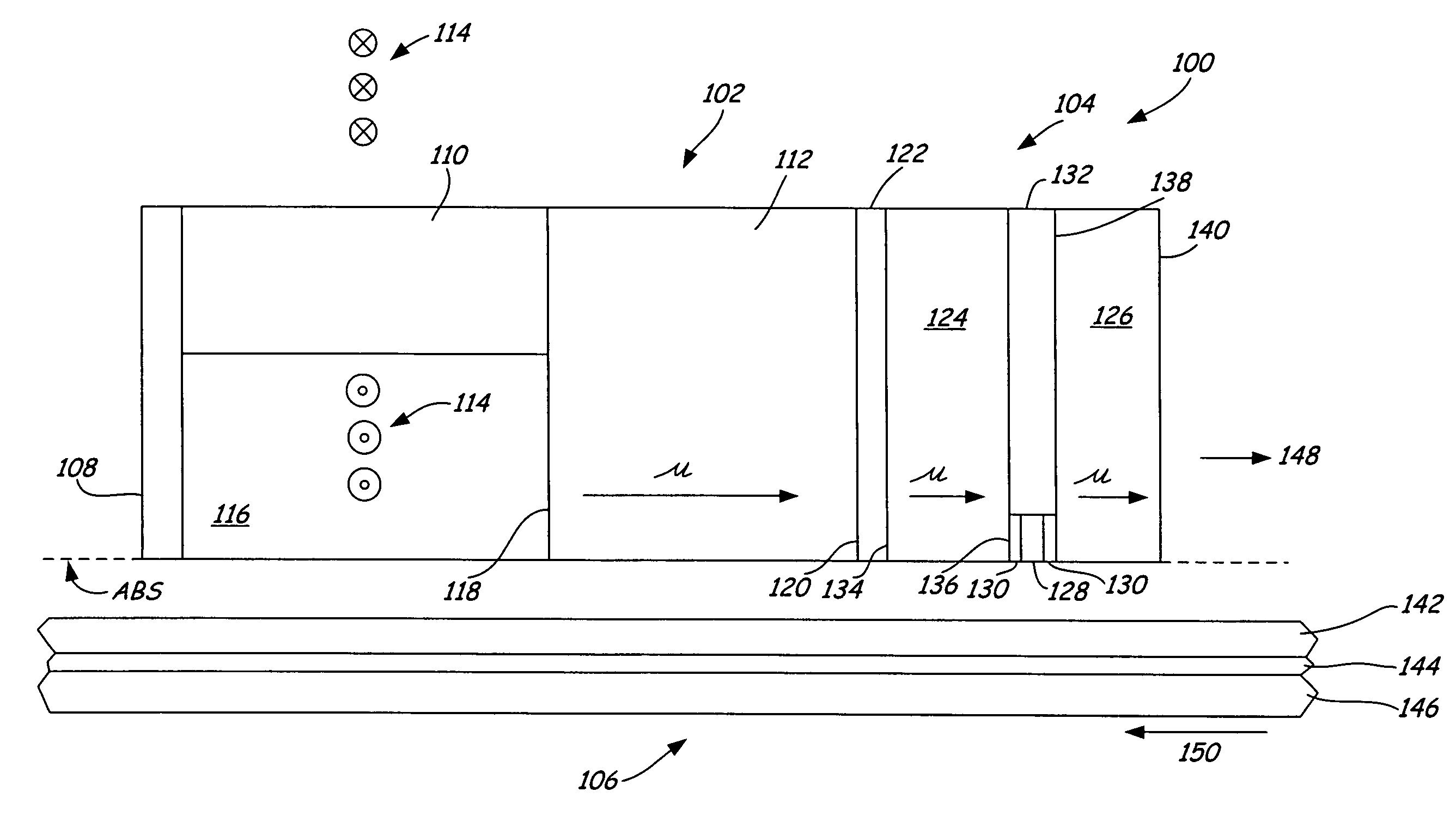
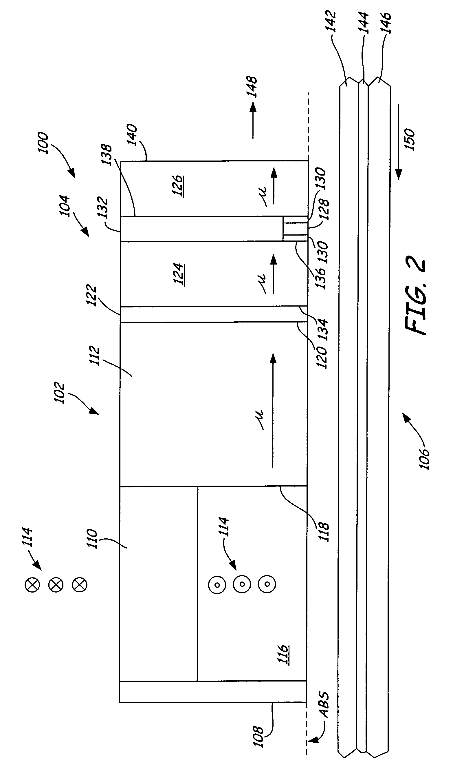
[0020]The present invention recognizes that side writing at a trailing edge of a magnetic element of a transducing head is reduced by varying permeability of magnetic material forming the magnetic element, with a lowest permeability at a trailing edge of the magnetic element and a highest permeability at a leading edge of the magnetic element. The magnetic element is any element of the transducing head that provides a potential return path for a magnetic field produced by the main pole, and may be a shared pole, or in the case that a transducing head is not arranged in a merged configuration, the magnetic element may be a return pole or reader shield. Performance of a main pole of the perpendicular writer is not substantially effected by varying permeability of the magnetic element. The concept of the present invention may be applied in any perpendicular writer having a main pole and at least one return pole, as exemplified herein in detail, without any suggestion of limiting or res...


PUM

PropertyMeasurementUnit
thicknessaaaaaaaaaa
permeabilityaaaaaaaaaa
shapeaaaaaaaaaa

Abstract

A transducing head has a main pole and at least one magnetic element (such as a return pole or a shield) which provides a potential return path for a magnetic field produced by the main pole. The magnetic element is spaced from the main pole. The magnetic element has a first edge closest to the main pole and a second edge furthest from the main pole. Permeability of the magnetic element increases from the first edge to the second edge.

Description

CROSS-REFERENCE TO RELATED APPLICATION(S)[0001]None.BACKGROUND OF THE INVENTION[0002]The present invention relates generally to the field of magnetic data storage and retrieval systems. More particularly, the present invention relates to a transducing head having a perpendicular writer portion in which side-writing is reduced significantly as compared to existing transducing head designs.[0003]A transducing head of a magnetic data storage and retrieval system typically includes a writer portion for storing magnetically-encoded data on a magnetic medium and a reader portion for retrieving the magnetically-encoded data stored on the magnetic medium. The reader portion is positioned adjacent the writer portion. The writer portion may be a perpendicular writer or a longitudinal writer. In either case, the general structure of the writer is similar, although the actual operation and dimensions of its elements will differ substantially. In a longitudinal writer, the poles are commonly ref...

Claims


Application Information

Patent Timeline
Patent Type & Authority Patents(United States)
IPC IPC(8): G11B5/31G11B5/11G11B5/39G11B5/265G11B5/127
CPCG11B5/1274G11B5/1278
Inventor AMIN, NURULZHOU, YUMINGGAO, KAIZHONGRYAN, PATRICK J.KALDERON, STEVENXUE, SONG S.LI, SHAOPINGKIEF, MARK T.
Owner SEAGATE TECH LLC
Why Eureka
Try Eureka