X-ray detector panel methods and apparatus

a detector panel and detector technology, applied in the field of methods and apparatus for digital xray imaging systems, can solve the problems of inability to rework the panel connection, and inability to transfer shock from the support to the fragile glass panel

Active Publication Date: 2008-07-08
GENERAL ELECTRIC CO
View PDF19 Cites 12 Cited by
  • Summary
  • Abstract
  • Description
  • Claims
  • Application Information

AI Technical Summary

Problems solved by technology

Being glass, the panel is inherently fragile and difficult to constrain.
A disadvantage of bonding the glass permanently to a support is the inability to rework the panel connections in case of damage or failure.
Another disadvantage of bonding the glass directly to a support is the direction transfer of shock from the support to the fragile glass panel.

Method used


Image

  • X-ray detector panel methods and apparatus
  • X-ray detector panel methods and apparatus
  • X-ray detector panel methods and apparatus

Examples


Embodiment Construction

[0010]There are herein provided methods and apparatus useful for imaging systems such as, for example, but not limited to a digital x-ray system. The apparatus and methods are illustrated with reference to the figures wherein similar numbers indicate the same elements in all figures. Such figures are intended to be illustrative rather than limiting and are included herewith to facilitate explanation of an exemplary embodiment of the apparatus and methods of the invention.

[0011]As used herein, an element or step recited in the singular and proceeded with the word “a” or “an” should be understood as not excluding plural said elements or steps, unless such exclusion is explicitly recited. Furthermore, references to “one embodiment” of the present invention are not intended to be interpreted as excluding the existence of additional embodiments that also incorporate the recited features.

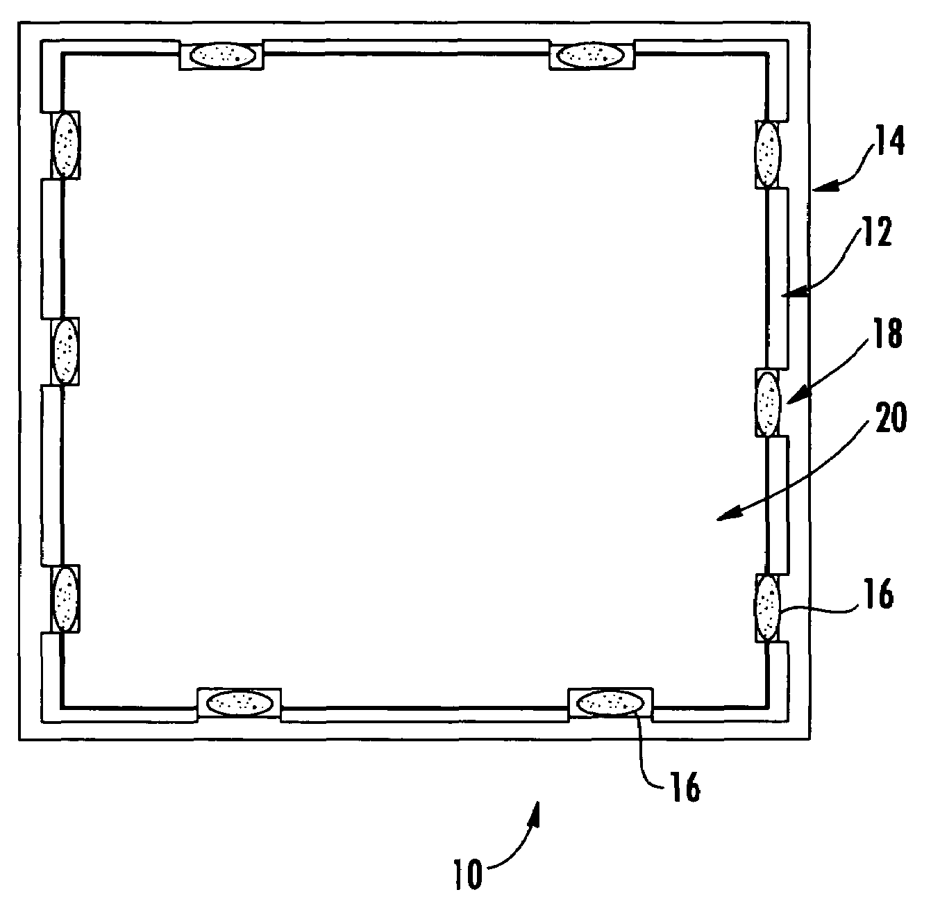
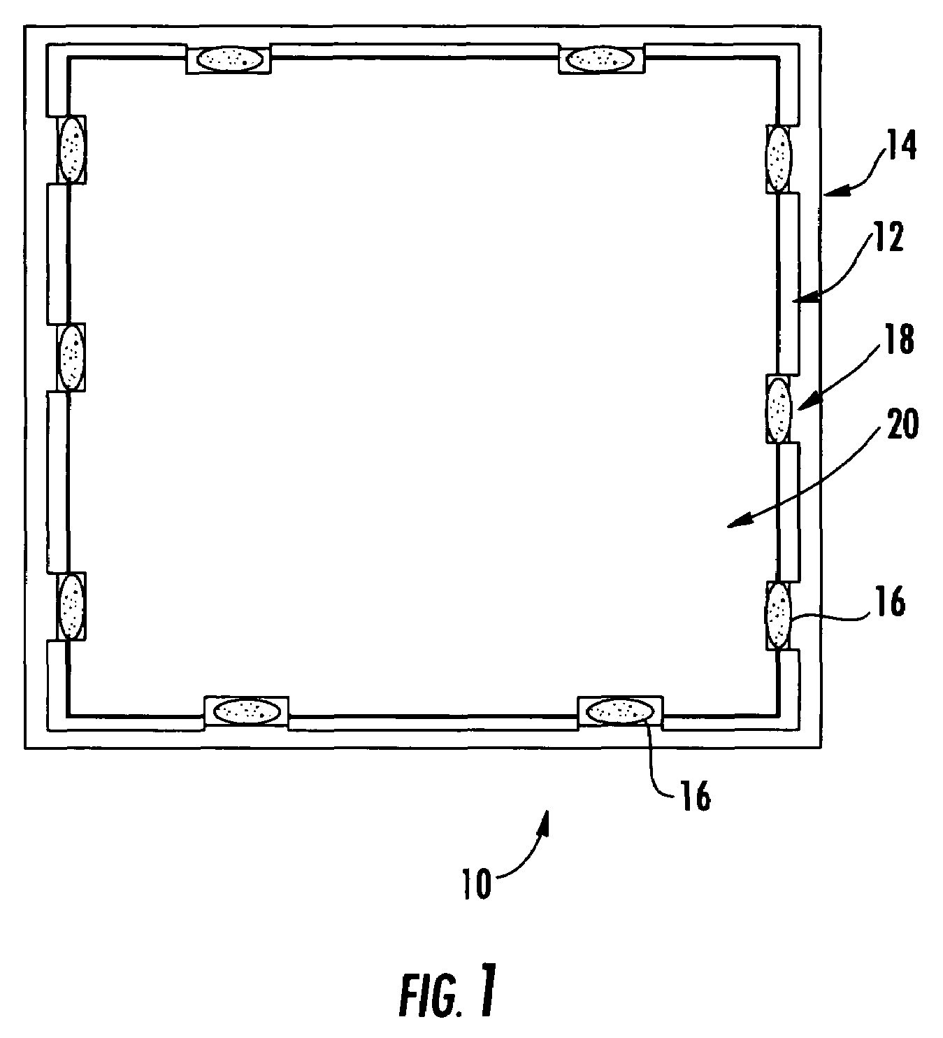
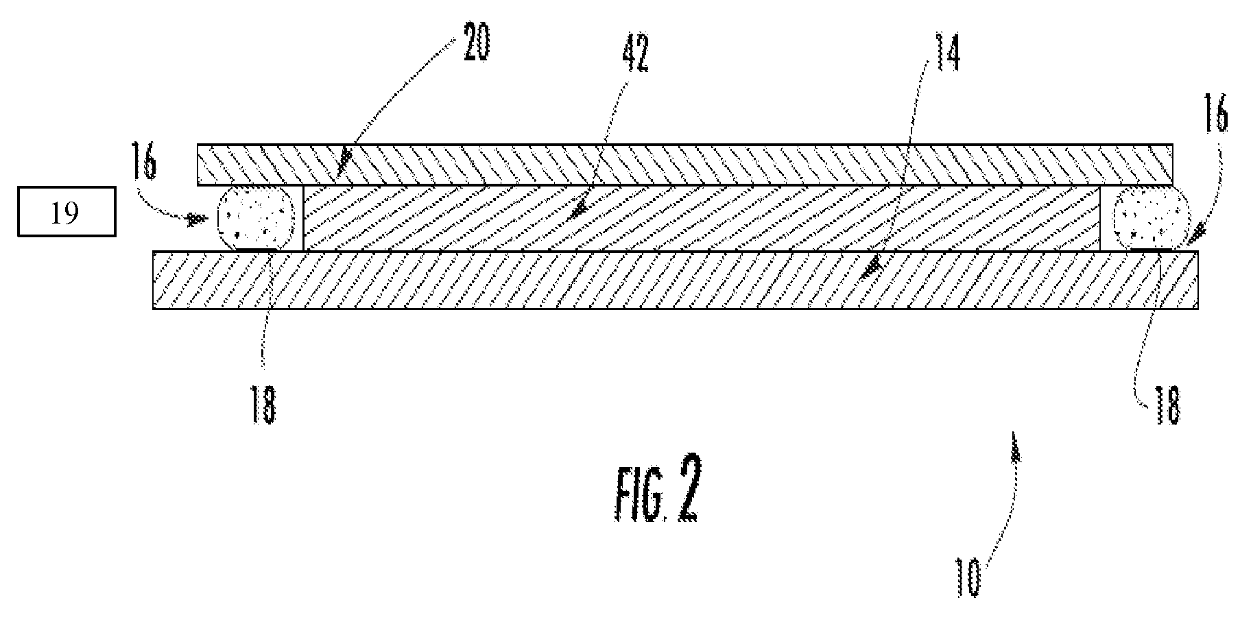
[0012]FIG. 1 is a top plan view and FIG. 2 is a cross-sectional view of a portable detector assembly 1...


PUM


Abstract

Apparatus includes a digital x-ray detector panel, a panel support, and a resilient sheet positioned between the panel and the support, the sheet having an area smaller than an area of the panel.

Description

BACKGROUND OF THE INVENTION[0001]This invention relates generally to methods and apparatus for digital x-ray imaging systems, and more particularly to methods and apparatus for digital x-ray panels.[0002]The panel of a digital x-ray detector generally consists of a glass substrate, upon which the imaging electronics and x-ray conversion materials are deposited. Being glass, the panel is inherently fragile and difficult to constrain. The panel is typically constrained using high-friction materials on its backside to resist lateral (in-plane) motion, or clamping / screwing the connecting electronics to a rigid support and relying on the flex connections to constrain the panel. In some instances the panel is permanently glued to a panel support or frame made of a metallic or plastic material to enable more general mechanical constraints. A disadvantage of bonding the glass permanently to a support is the inability to rework the panel connections in case of damage or failure. Another disa...

Claims


Application Information

Patent Timeline
Patent Type & Authority Patents(United States)
IPC IPC(8): G21K4/00G03B42/04
CPCA61B6/102
Inventor UTSCHIG, MICHAEL JOHNGALIE, JESSICA ANNEERTEL, JASON ROBERT
Owner GENERAL ELECTRIC CO
Why Eureka
Try Eureka