Weight adjustment member for golf club head

a technology of weight adjustment and golf club head, which is applied in the field of golf club equipment, can solve problems such as less than desirable appearan

Active Publication Date: 2008-07-08
KARSTEN MFG CORP
View PDF10 Cites 271 Cited by
  • Summary
  • Abstract
  • Description
  • Claims
  • Application Information

AI Technical Summary

Problems solved by technology

Additionally, the adhesive, while not escaping the tuning port, may be visible between the weight adjustment member and the tuning port wall, resulting in a less than desirable appearance.

Method used


Image

  • Weight adjustment member for golf club head
  • Weight adjustment member for golf club head
  • Weight adjustment member for golf club head

Examples


Embodiment Construction

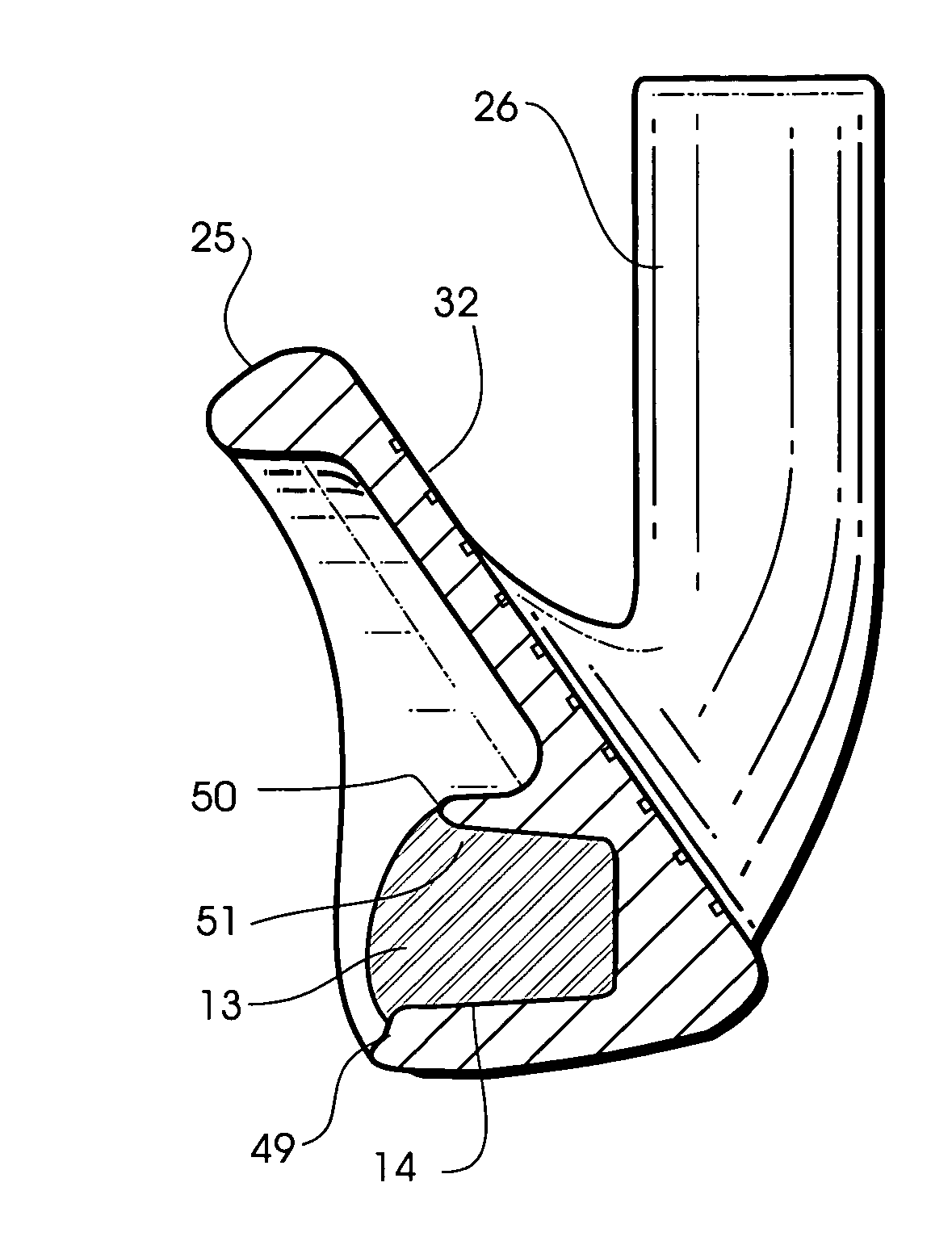
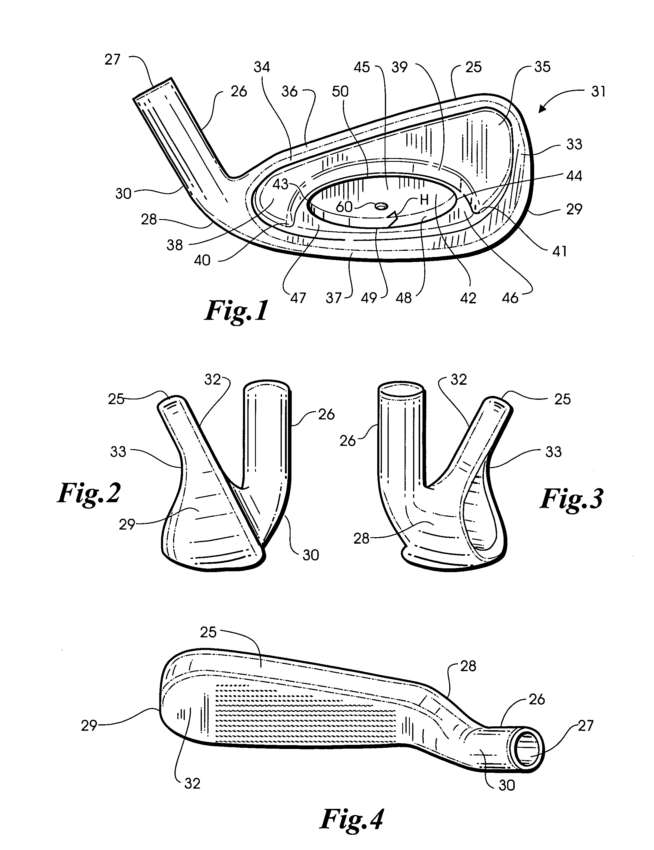
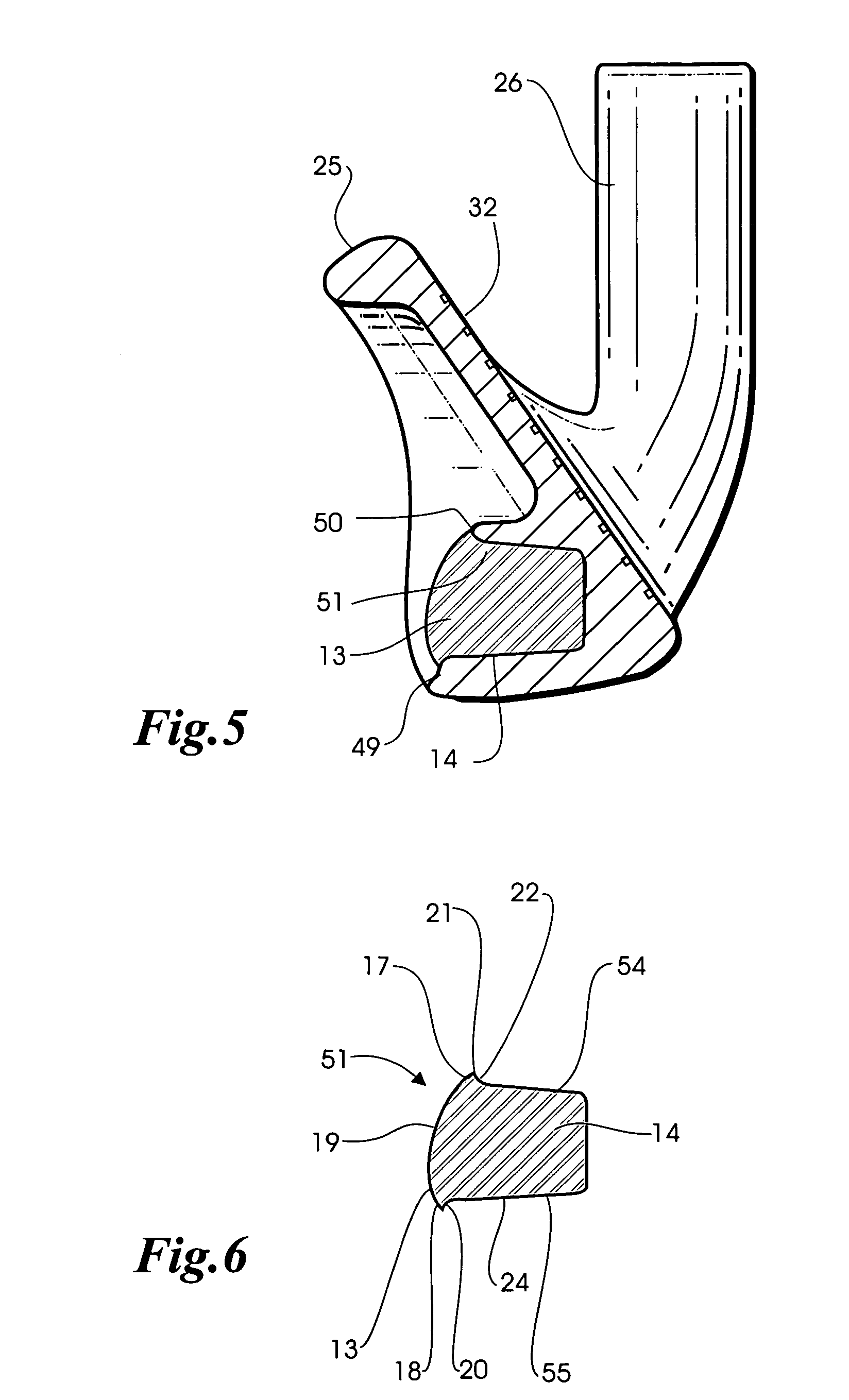
[0016]Referring to FIGS. 1-4, an iron-type golf club head 31 includes a body 25 and a hosel 26 containing a cylindrical bore 27 for receiving one end of a golf club shaft (not shown). The body 25 has a heel portion 28 and a toe portion 29 that are spaced apart. The hosel 26 includes a neck 30 connected to the heel portion 28 of the body 25. The club head 31 is preferably cast from suitable metal such as stainless steel. A front face 32 arranged for impact with a golf ball (not shown) is provided on the body 25 and extends between the body heel and toe portions 28, 29 along a frontal portion of the body 25. Disposed rearwardly of the front face 32 is a back face 33.

[0017]In the iron type golf club head 31 shown in FIG. 14, a perimeter weighting element 34 protrudes rearwardly from the front face 32 and defines a primary cavity 35 in the back face 33. The primary cavity 35 is defined at its upper extremity by a top rail 36 and at its lower extremity by a sole 37. The top rail 36 exten...


PUM


Abstract

A weight adjustment member may be mounted in a tuning port in a golf club head and secured therein using adhesive. The weight adjustment member includes a lip which prevents excess adhesive from escaping the tuning port and hides adhesive that might otherwise be visible between the weight adjustment member and the tuning port. Locating devices that mate with each other are included in the tuning port and on the weight adjustment member. A method of mounting the weight adjustment member in the tuning port of a golf club head is also provided.

Description

BACKGROUND OF THE INVENTION[0001]The present invention relates generally to golf equipment and, in particular, to a weight adjustment member for a golf club head.[0002]U.S. Pat. No. 6,206,790 to D. J. Kubica et al discloses an iron-type golf club head having a primary cavity formed in its back face by a perimeter weighting element which protrudes rearwardly from its front face. A secondary cavity or tuning port defined within the primary cavity contains a weight adjustment member. In the Kubica patent, the weight adjustment member comprises a top surface, a bottom surface, and a side surface extending between said top and bottom surfaces with a groove formed in the side surface extending peripherally of the weight adjustment member. According to the Kubica patent, if epoxy is applied to the bottom of the weight adjustment member in order to affix the weight adjustment member in the tuning port, any excess epoxy collects in the groove and is prevented from being pushed out of the sec...

Claims


Application Information

Patent Timeline
Patent Type & Authority Patents(United States)
IPC IPC(8): A63B53/04A63B53/06
CPCA63B53/047A63B2053/0491A63B60/02
Inventor NICOLETTE, MICHAEL R.SOLHEIM, JOHN A.SCHWEIGERT, BRADLEY D.
Owner KARSTEN MFG CORP
Why Eureka
Try Eureka