Backscatter inspection portal

a technology of backscatter and inspection portal, which is applied in the direction of material analysis using wave/particle radiation, x/gamma/cosmic radiation measurement, instruments, etc., can solve the problems of image degradation, imager's ability, and the size of the overall system to increas

Active Publication Date: 2008-07-15
AMERICAN SCI & ENG INC
View PDF23 Cites 192 Cited by
  • Summary
  • Abstract
  • Description
  • Claims
  • Application Information

AI Technical Summary

Problems solved by technology

This may result in interference, or cross-talk, between respective imaging systems, resulting in image degradation.
This is due to the lack of each flying-spot imager's ability to distinguish the origin of the scattered radiation from each imager's source.
This approach causes the size of the overall system to increase.
In space-limited applications, this is often undesirable.

Method used


Image

  • Backscatter inspection portal
  • Backscatter inspection portal
  • Backscatter inspection portal

Examples


Embodiment Construction

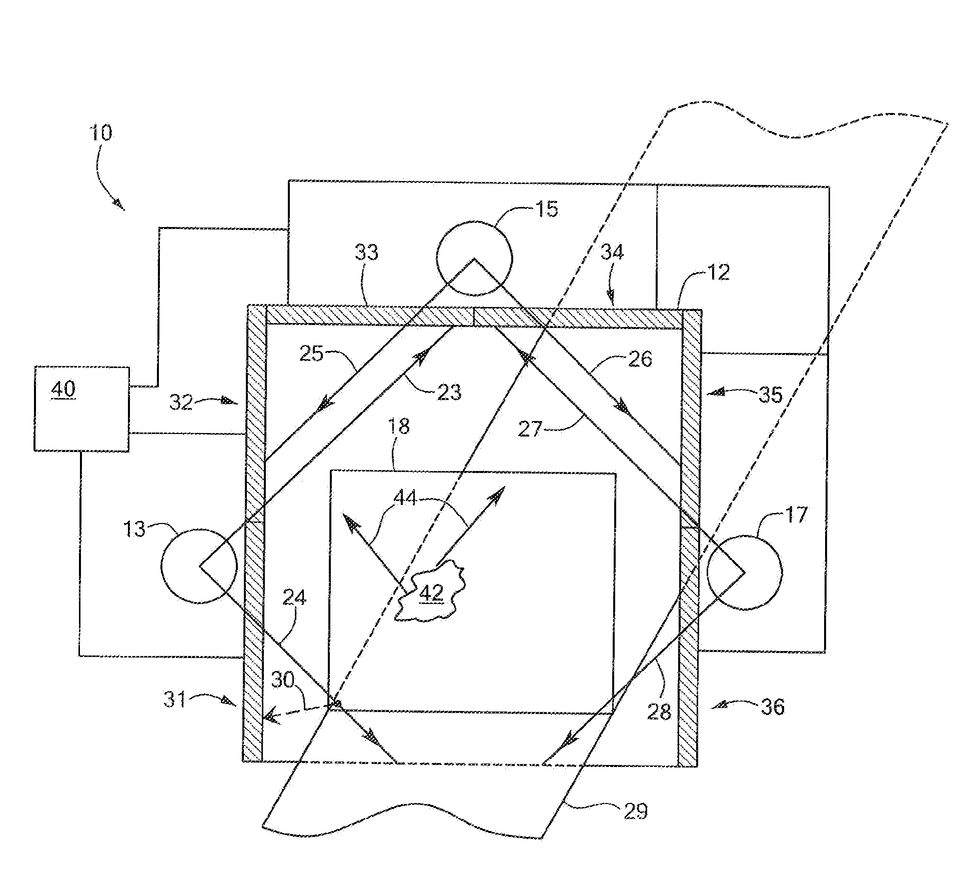
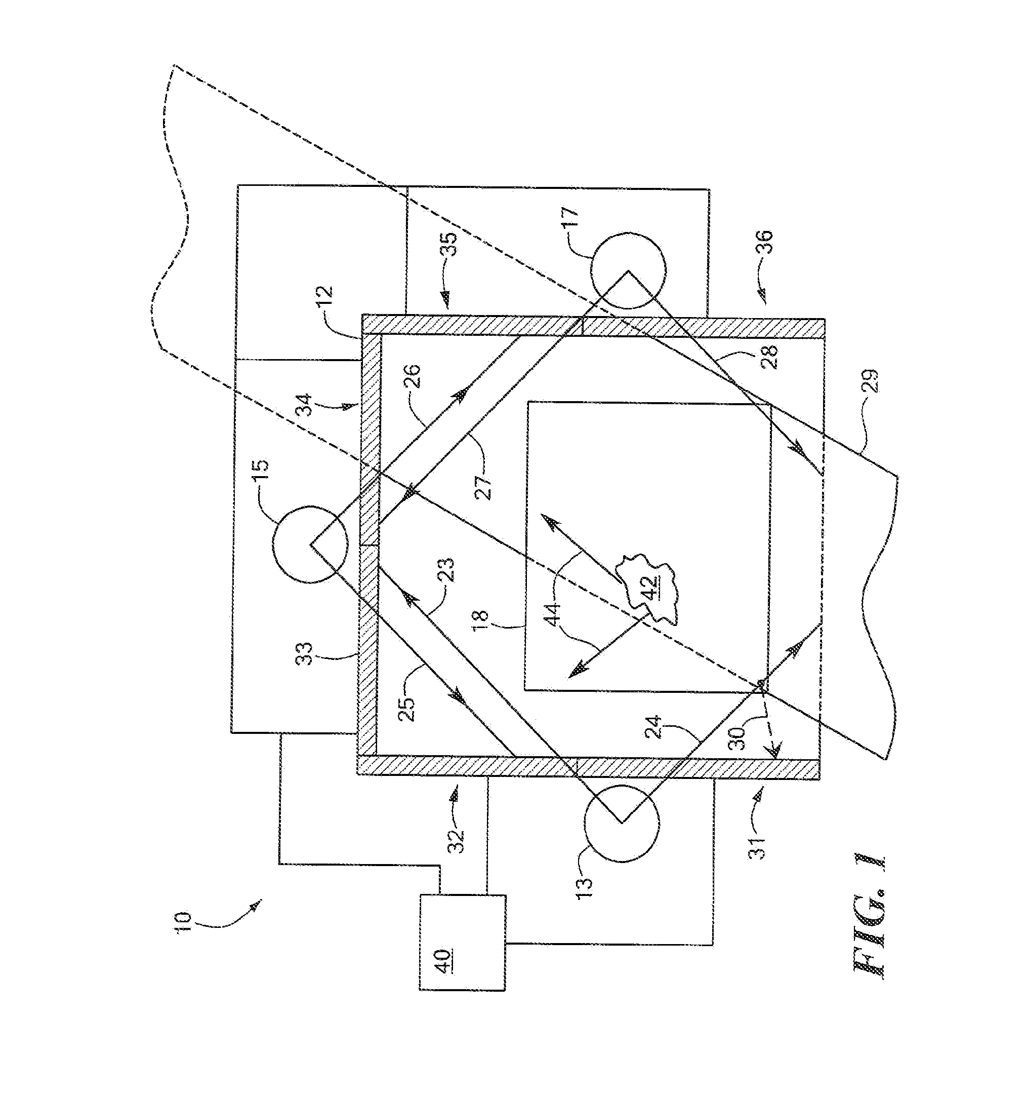
[0017]In accordance with embodiments of the present invention, beam cross talk is minimized between or among multiple flying-spot backscatter imaging systems configured as a multi-view backscatter inspection system, with no restriction on the distance between the individual imaging systems. In other words, in a multi-view system comprised of individual backscatter imaging systems for each view, the individual imaging systems can be placed as close together as is physically possible, while cross talk is advantageously reduced or eliminated.

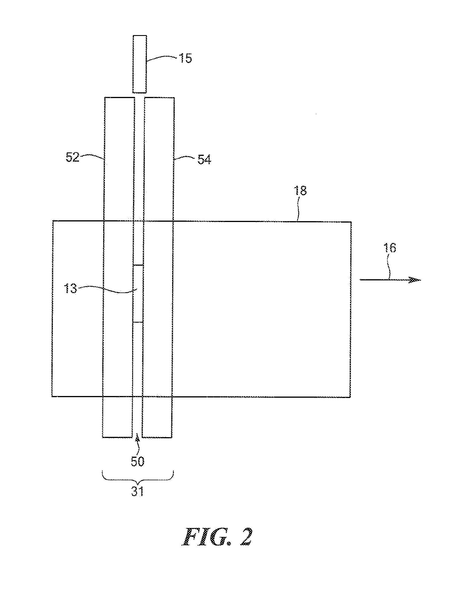
[0018]Methods and advantages of backscatter inspection of a moving vehicle by illuminating the vehicles with x-rays from either above or beneath the moving vehicle are described in U.S. Pat. No. 6,249,567, issued Jun. 19, 2001, which is incorporated herein by reference. In an embodiment of the aforesaid patent, illustrated in FIG. 3, rotating chopper wheel 20 is used to develop a pencil beam 14 which may be swept in a plane substantially parallel t...


PUM

PropertyMeasurementUnit
phaseaaaaaaaaaa
phase relationshipaaaaaaaaaa
backscatter imagingaaaaaaaaaa

Abstract

A system and method for inspecting an object with multiple sources of penetrating radiation. Irradiation of the inspected object by the sources is temporally sequenced such that the source of detected scattered radiation is unambiguous. Thus, multiple views of the inspected object may be obtained and image quality may be enhanced, even in a compact geometry in which the beams are substantially coplanar.

Description

[0001]The present application claims priority from U.S. Provisional Application No. 60 / 561,079, filed Apr. 9, 2004, which is incorporated herein by reference.TECHNICAL FIELD[0002]The present invention relates to systems and methods for inspecting objects with penetrating radiation, and, more particularly, the invention relates to inspection systems employing multiple sources of radiation.BACKGROUND ART[0003]It is desirable to determine the presence of objects, such as contraband, weapons, or explosives, that have been concealed, for example, in a moving vehicle, or on a person, or in any inspected object, while the inspected object is moved past one or more systems that image the contents of the object using penetrating radiation. The determination should be capable of being made while the inspected object is in motion, or, alternatively, while the inspection system is in motion with respect to the inspected person or object. Indeed, since inspection rate, and thus hourly throughput...

Claims


Application Information

Patent Timeline
Patent Type & Authority Patents(United States)
IPC IPC(8): G01N23/201G01N23/203G01N23/04G01N23/20G01V5/00
CPCG01V5/0025G01N23/20G01T1/167
Inventor CASON, W. RANDALL
Owner AMERICAN SCI & ENG INC
Why Eureka
Try Eureka