X-ray ambient level safety system

a safety system and ambient radiation technology, applied in the direction of irradiation devices, electrical equipment, nuclear engineering, etc., can solve the problems of increasing the ambient radiation, adding to the requisite weight and cost of the system, and increasing the radiation

Inactive Publication Date: 2000-05-23
SILICON VALLEY BANK
View PDF1 Cites 179 Cited by
  • Summary
  • Abstract
  • Description
  • Claims
  • Application Information

AI Technical Summary

Problems solved by technology

However, if the container is only lightly loaded, ambient radiation may increase substantially.
If both the characteristic energy of the x-ray beam and its power are maintained constant, then the system must be shielded to account for the empty-container "worst case" level of ambient radiation, substantially adding to the requisite weight and cost of the system.

Method used


Image

  • X-ray ambient level safety system

Examples


Embodiment Construction

The invention will be described in terms of a preferred embodiment as applied, without limitation, to a mobile x-ray system for the inspection of trucks, as described in U.S. patent application Ser. No. 08 / 799,533, filed Feb. 12, 1997, and hereby incorporated by reference. In this application, the mobile x-ray inspection system moves past stationary containers such as trucks and produces x-ray images of the contents of the containers.

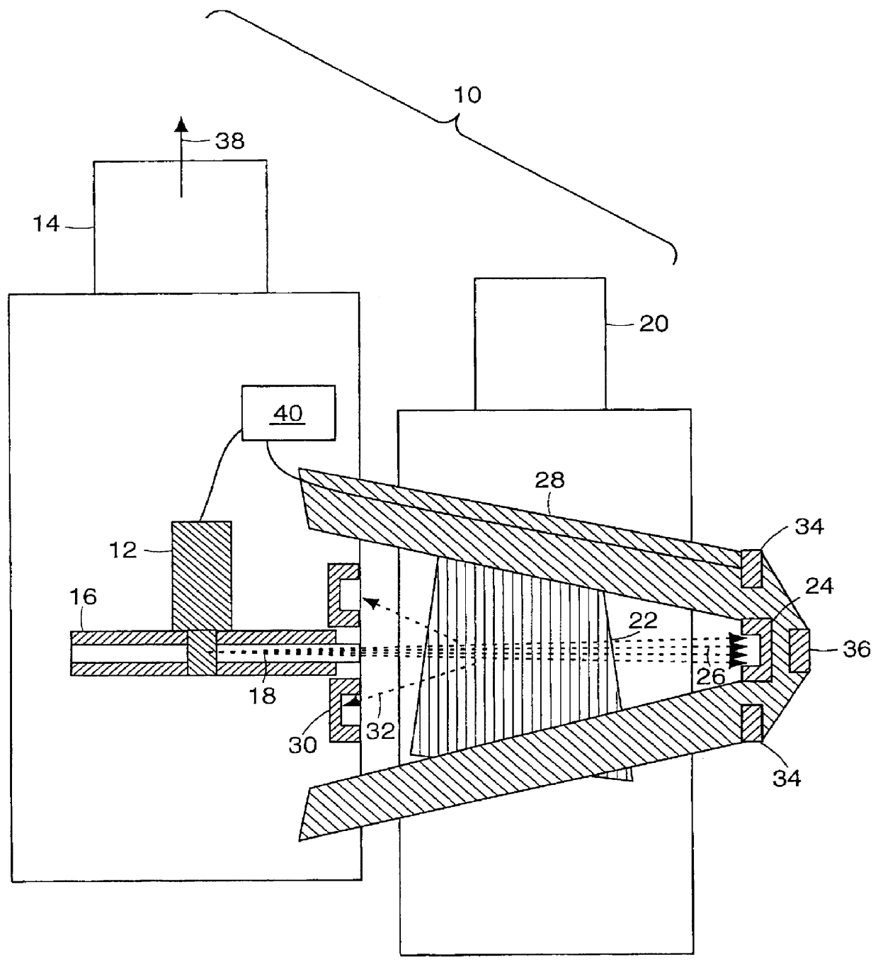
Referring to FIG. 1, a schematic top view is shown of an x-ray inspection system designated generally by numeral 10. A source (or generator) 12 of penetrating radiation, typically x-rays, is enclosed within mobile unit 14, which may be a truck, by way of example. Scanning mechanism 16, which may be a wheel with hollow spokes or another scanning mechanism known to persons skilled in the art, forms an x-ray beam 18 that scans the inspected container 20, shown here, by way of example, as a truck. Container 20 holds cargo 22 which is traversed by x-ray beam...


PUM

PropertyMeasurementUnit
energyaaaaaaaaaa
radial distanceaaaaaaaaaa
energy distributionaaaaaaaaaa

Abstract

A method for modulating the intensity of an x-ray beam in an x-ray inspection system so as to maintain the highest penetration power and optimum image quality subject to keeping the ambient radiation generated by the x-rays below a specified standard.

Description

TECHNICAL FIELDThe present invention relates to the maintenance of safe ambient levels of x-ray exposure in the presence of x-ray equipment, and, more particularly, to the active control of x-ray source characteristics based on the monitoring of ambient radiation.BACKGROUND OF THE INVENTIONX-ray systems are commonly employed for such applications as the inspection of containers by forming a quantitative image of the intensity of the x-rays transmitted through the containers. To form the image it is necessary that the x-ray beam be characterized by photons of sufficient energy and a flux of sufficient intensity (photons per unit area per unit time) that the beam may penetrate the most heavily loaded portions of the container undergoing inspection, and deliver sufficient intensity to the detectors of the transmitted beam that adequate signal-to-noise may be achieved during the scan time so that images of adequate quality may be obtained. For a given energy distribution of x-rays, the ...

Claims


Application Information

Patent Timeline
Patent Type & Authority Patents(United States)
IPC IPC(8): G01N23/02H05G1/46H05G1/00H05G1/44G21K5/10
CPCG01N23/02H05G1/46H05G1/44G21K5/10
Inventor GRODZINS, LEEHUANG, SUZHOUSAPP, WILLIAM WADEADAMS, WILLIAM
Owner SILICON VALLEY BANK
Why Eureka
Try Eureka