
Wavelength dispersive XRF system using focusing optic for excitation and a focusing monochromator for collection

a focusing monochromator and wavelength dispersive technology, applied in the field of xray fluorescence (xrf) spectroscopy systems, can solve the problems of poor sensitivity, poor energy resolution, and vacancies that destabilize the atoms

Inactive Publication Date: 2005-08-23
X-RAY OPTICAL SYSTEM INC
View PDF18 Cites 124 Cited by
  • Summary
  • Abstract
  • Description
  • Claims
  • Application Information

AI Technical Summary

Benefits of technology

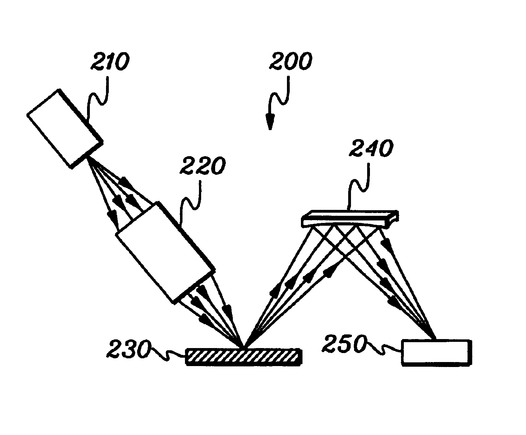
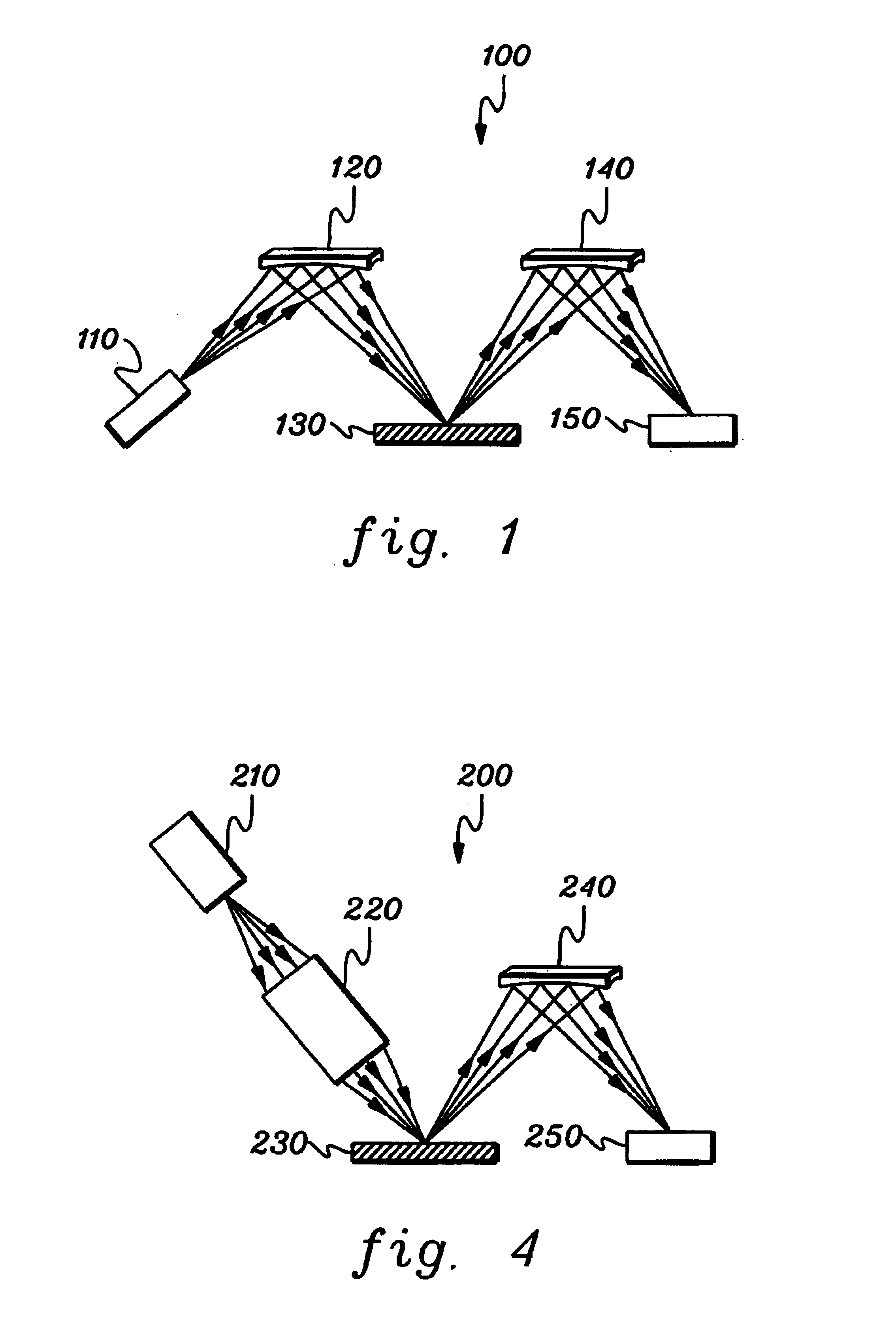
[0024]The shortcomings of the prior approaches are overcome, and additional advantages are provided, by the present invention which in one aspect comprises an x-ray fluorescence (XRF) spectroscopy system. The XRF system includes at least one source of x-ray radiation and at least one excitation optic disposed between the at least one x-ray radiation source and the sample. The at least one excitation optic collects x-ray radiation from the at least one source and focuses the x-ray radiation to a focal point on the sample to incite at least one analyte in the sample to fluoresce. The system further includes at least one x-ray detector and at least one collection optic. The at least one collection optic comprises at least one doubly curved diffracting optic disposed between the sample and the at least one x-ray detector for collecting x-ray fluorescence from the focal point on the sample and directing the fluorescent x-rays towards the at least one x-ray detector.

Problems solved by technology

As x-ray photons strike the sample, they knock electrons out of the inner shell of the atoms that make up the sample, creating vacancies that destabilize the atoms.
There are disadvantages to XRF / EDS systems, however, including relatively poor sensitivity and poor energy resolution.
However, there are disadvantages to conventional XRF / WDS systems, including a requirement for a high power x-ray tube due to limitations of the WDS approach that result in a low efficiency, and a small collection solid angle.
Another disadvantage of a conventional WDS system is that the crystal or multi-layer structure on the collection side only selects a specific x-ray wavelength and a scanning mechanism or multi-crystal system is needed for multi-element detection.
This has the advantage that detector saturation may be avoided, but it results in a complicated alignment.
Therefore, XRF / WDS systems are typically bulky, complex, and more expensive as compared to XRF / EDS systems.

Method used


Image

  • Wavelength dispersive XRF system using focusing optic for excitation and a focusing monochromator for collection
  • Wavelength dispersive XRF system using focusing optic for excitation and a focusing monochromator for collection
  • Wavelength dispersive XRF system using focusing optic for excitation and a focusing monochromator for collection

Examples


Embodiment Construction

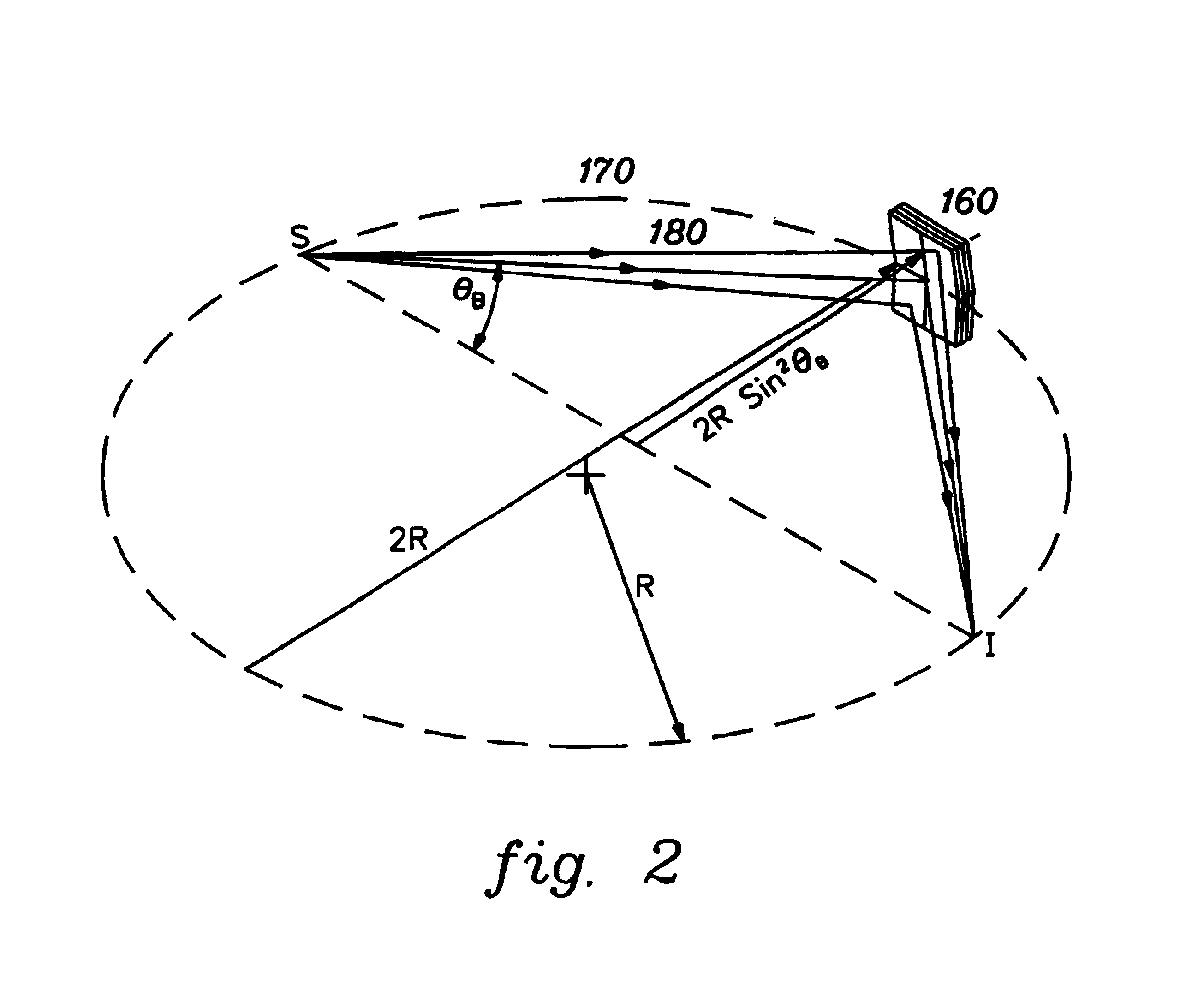
[0036]Generally stated, one embodiment of a compact XRF / WDS system in accordance with an aspect of the present invention comprises an x-ray source, an excitation x-ray optic that focuses x-rays onto a sample from the source, at least one collection monochromator and an x-ray counter. The excitation x-ray optic can be a focusing polycapillary optic that provides polychromatic excitation or a point-focusing doubly curved crystal optic that provides monochromatic excitation. The collection monochromator (which can be a doubly curved crystal optic, a doubly curved multi-layer optic, or other doubly curved diffracting optic) selects a desired characteristic wavelength of an element. The intensity of the reflected x-rays is measured by a detector and is correlated to the concentration of this element in the specimen.

[0037]One aspect of an XRF / WDS system in accordance with the present invention is that the excitation optic can efficiently capture a large cone angle of x-rays from a point x...


PUM


Abstract

X-ray fluorescence (XRF) spectroscopy systems and methods are provided. One system includes a source of x-ray radiation and an excitation optic disposed between the x-ray radiation source and the sample for collecting x-ray radiation from the source and focusing the x-ray radiation to a focal point on the sample to incite at least one analyte in the sample to fluoresce. The system further includes an x-ray fluorescence detector and a collection optic comprising a doubly curved diffracting optic disposed between the sample and the x-ray fluorescence detector for collecting x-ray fluorescence from the focal point on the sample and focusing the fluorescent x-rays towards the x-ray fluorescence detector.

Description

CROSS-REFERENCE TO RELATED PATENTS / APPLICATIONS[0001]This application is a continuation of PCT application PCT / US02 / 19272 filed Jun. 18, 2002, and published under PCT Article 21(2) in English as WO 02 / 103710 A2 on Dec. 27, 2002. PCT / US02 / 19272 claimed the priority of U.S. provisional application 60 / 299,371, filed Jun. 19, 2001. The entire disclosures of both are incorporated herein by reference. This application also contains subject matter which relates to the subject matter of the following commonly-owned patents and applications, each of which is hereby incorporated herein by reference in its entirety:[0002]“Use Of A Kumakhov Lens For X-Ray Lithography”, by Muradin A. Kumakhov, U.S. Pat. No. 5,175,755, issued Dec. 29, 1992;[0003]“Device For Controlling Beams Of Particles, X-Ray and Gamma Quanta”, by Muradin A. Kumakhov, U.S. Pat. No. 5,192,869, issued Mar. 9, 1993;[0004]“Use Of A Kumakhov Lens In Analytic Instruments”, by Muradin A. Kumakhov, U.S. Pat. No. 5,497,008, issued Mar. ...

Claims


Application Information

Patent Timeline
IPC IPC(8): G01N23/22G01N23/223G21K4/00G01T1/36G21K1/00G21K1/06
CPCB82Y10/00G01N23/223G21K1/06G21K1/062G21K2201/064G01N2223/076
Inventor CHEN, ZEWUGIBSON, DAVID M.
Owner X-RAY OPTICAL SYSTEM INC
Learn More