

User interface design apparatus and method
a technology of user interface and design apparatus, applied in the direction of user interface execution, program control, instruments, etc., can solve the problem that text input imposes a load on the author
- Summary
- Abstract
- Description
- Claims
- Application Information
AI Technical Summary
Problems solved by technology
Method used
Image

Examples
embodiment 1
Alternative Embodiment 1
[0062]In the above embodiment, the properties in a semantic structure generating rule are presented to the author, and the author generates a specific semantic structural path by selecting a combination of properties. According to this method, the author may designate a correct vocabulary forming a path in a wrong order. In the semantic structure in FIG. 5, for example, the semantic structural path “ / number / pizza” which cannot be generated from this grammar may be designated. In order to prevent this, utterance information as virtual input information conforming to the speech recognition grammar may be automatically generated from the grammar, and a semantic structure generated when the utterance is input may be presented to the author. A case wherein such processing is introduced will be described below as alternative embodiment 1.
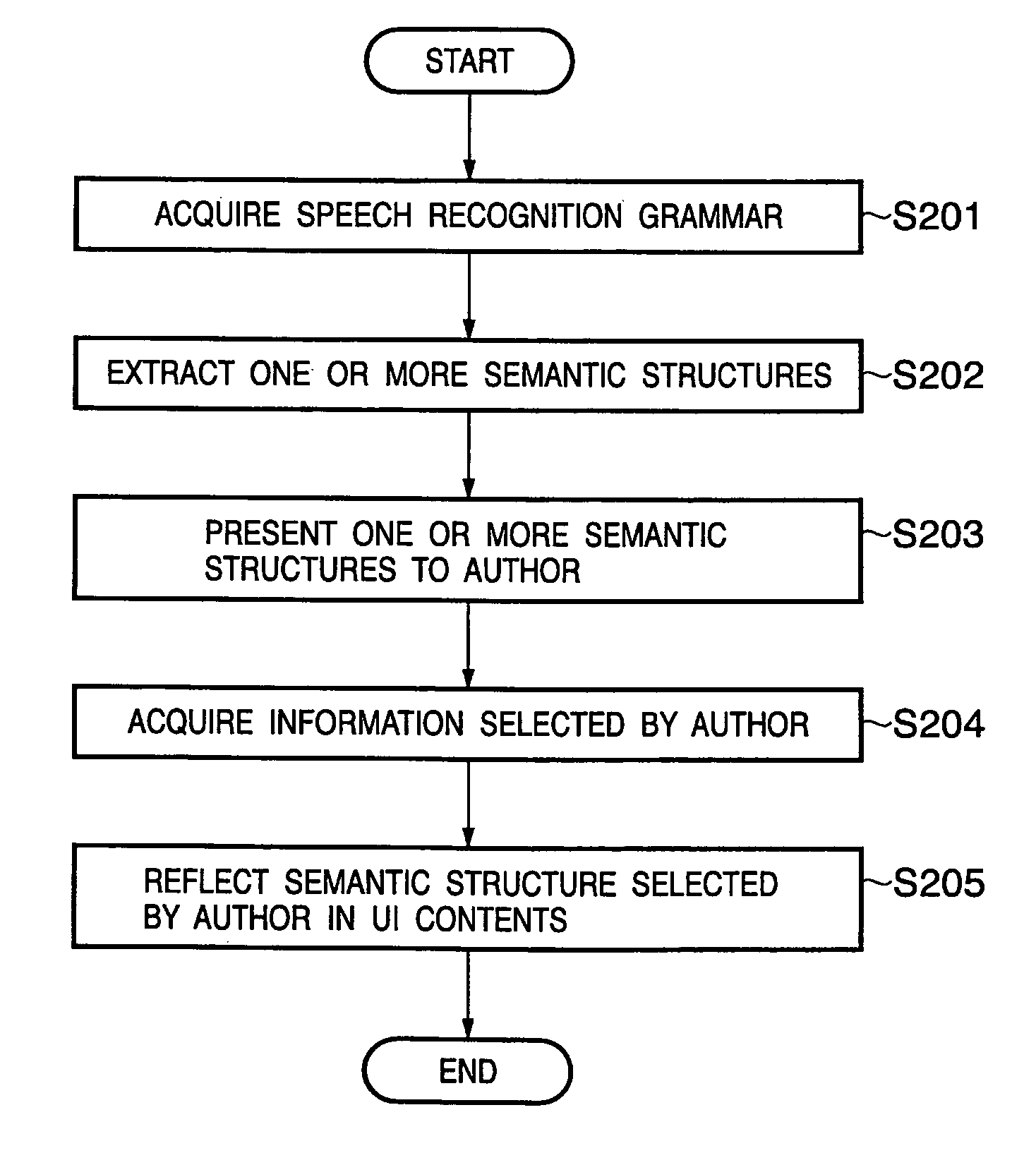
[0063]FIG. 10 is a flowchart showing UI design processing according to alternative embodiment 1.
[0064]When the author right-click...
embodiment 2
Alternative Embodiment 2
[0074]In alternative embodiment 1, an utterance example is automatically generated by the speech recognition grammar. In this method, however, a semantic structure intended by the author may not be included in M semantic structures presented by the apparatus. In order to solve this problem, M may be increased. If, however, M is increased, the load of searching for a semantic structure intended by the author increases. In alternative embodiment 2, therefore, semantic structures are generated by using the speech recognition grammar and utterance example information written in the grammar and are presented to the author.
[0075]FIG. 13 shows an example of a speech recognition grammar written by SRGS. In SRGS, the tag describing an utterance example is prepared, and the example written in this tag can be used as utterance example information. Reference numeral 1301 in FIG. 13 denotes an example of utterance example information.
[0076]Since the flow of processing in...
embodiment 3
Alternative Embodiment 3
[0078]In alternative embodiment 2, an utterance example is input at the time of the generation of a speech recognition grammar. It is, however, effective to input an utterance example at the time of the use of an authoring tool. FIG. 15 shows a flowchart of UI design processing which realizes such processing.
[0079]When the author right-clicks form 1 (704) in the window in FIG. 7 and selects “binding to speech recognition result” from a context menu, the flow in FIG. 15 starts. When this flow starts, first of all, a speech recognition grammar designating dialog 1601 shown in FIG. 16A is displayed, in which a speech recognition grammar name input by the author is acquired (step S1501). In the speech recognition grammar designating dialog 1601, a speech recognition button 1603 is also prepared. When the speech recognition button 1603 is pressed, an utterance from the author is acquired (step S1502). Speech recognition processing is then executed by using the spe...
PUM
 Abstract
Description
Claims
Application Information