Paddle sensor

a technology of paddle and sensor, applied in the field of paddle sensors, can solve the problems of electric motor overheating, easy wear and tear, and complex mechanical design of electric motors within the housing

Inactive Publication Date: 2008-08-19
BISHEL RICHARD A
View PDF67 Cites 20 Cited by
  • Summary
  • Abstract
  • Description
  • Claims
  • Application Information

AI Technical Summary

Problems solved by technology

They rely on the movement of the electric motor to engage mechanical contact switches which are prone to wear out and fail, causing the electric motor to overheat.
The movement of the electric motor within housing requires intricate mechanical design and is also p...

Method used


Image

  • Paddle sensor
  • Paddle sensor
  • Paddle sensor

Examples


Embodiment Construction

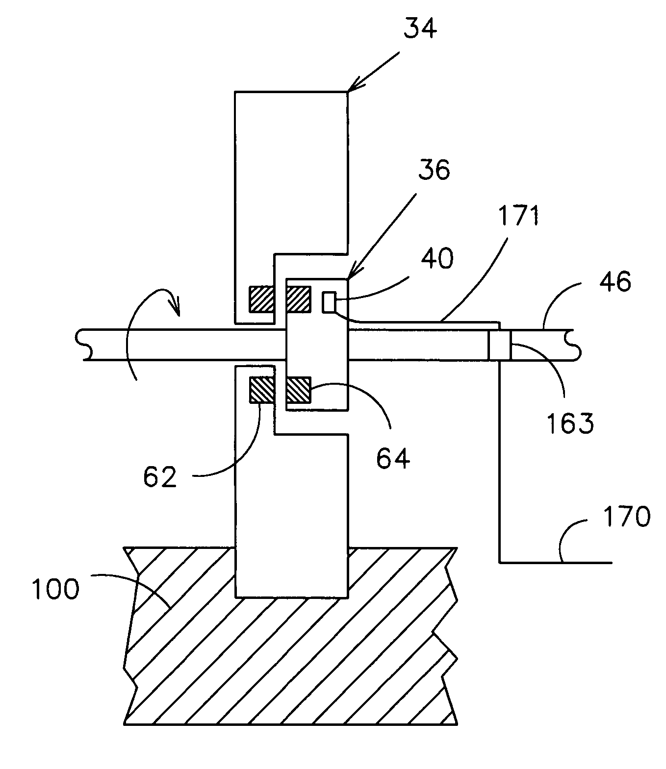
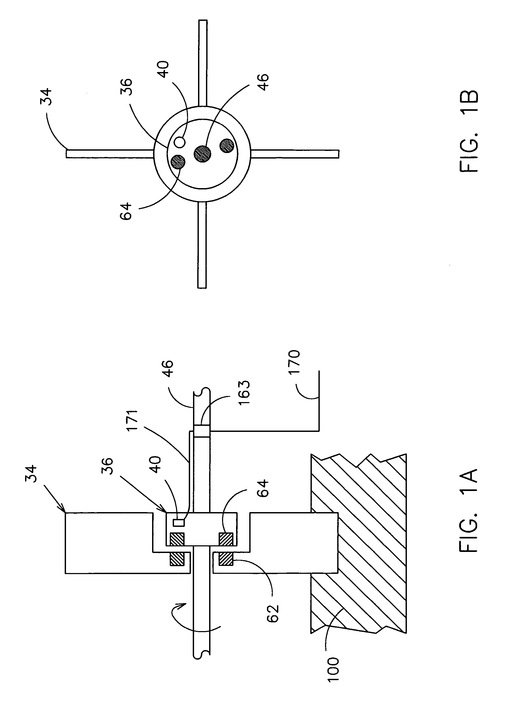
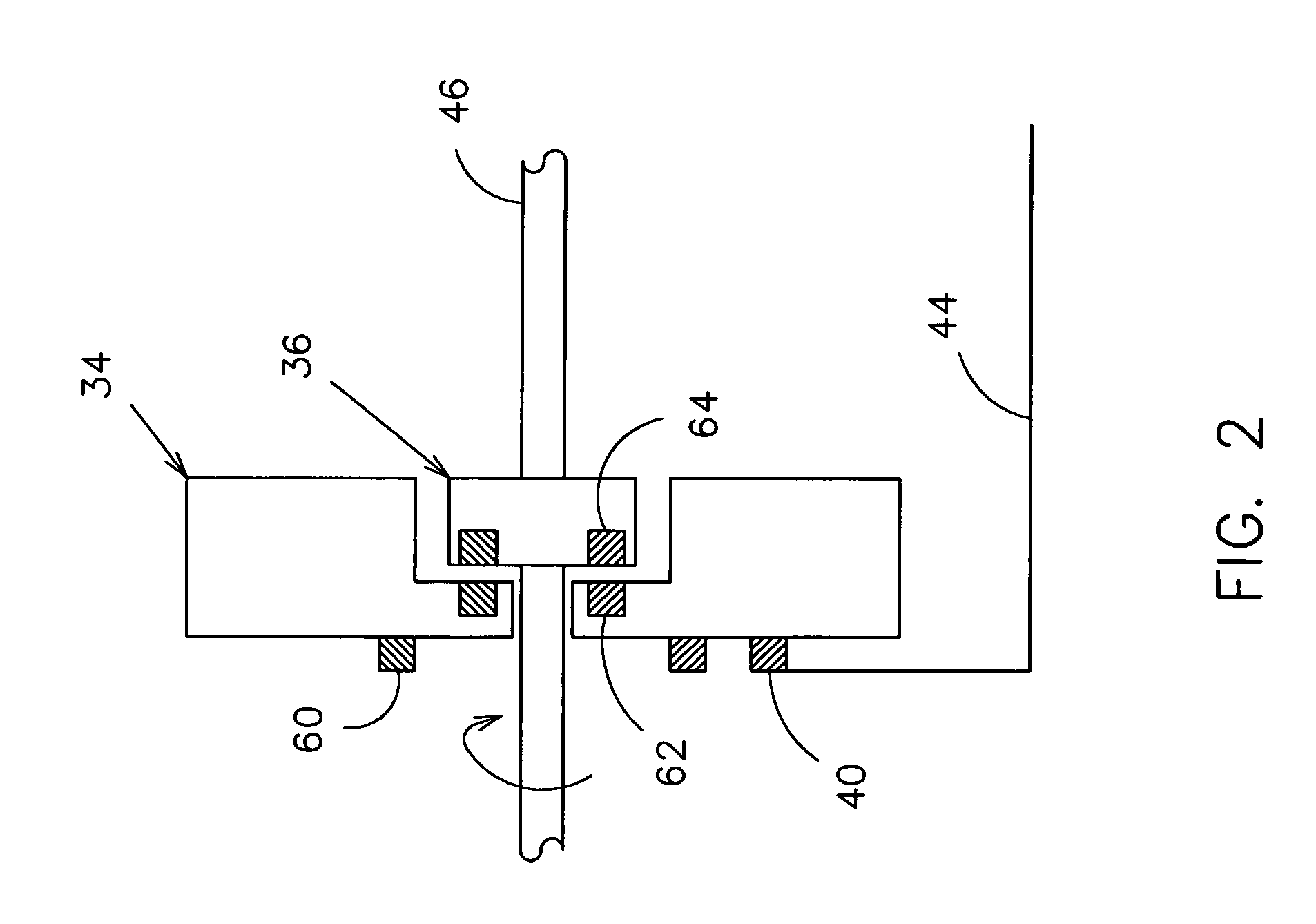
[0047]FIG. 1A shows a diagram of the preferred embodiment of the invention. A paddle 34 is installed on a rotating shaft 46 and coupled to the shaft's motion by a hub 36 which is physically connected to the rotating shaft 46. The coupling mechanism between the hub 36 and the paddle 34 is a magnetic attractive force between the permanent magnets 64 and the magnetic material 62 placed on the paddle 34. As the shaft 46 rotates, the paddle 34 rotates with the shaft 46 because of the magnetic coupling force. A hall-effect sensor 40 is mounted on the hub 36 that rotates with the shaft 46. In this configuration, the sensor 40 rotates with the shaft 46 and detects the relative motion between the paddle 34 and the shaft 46. The sensor output 170 which comes from the sensor 40, via wires 171 through the slip ring 163, gives relative motion and is zero when the shaft 46 and the paddle 34 are moving together. When a substance 100 is placed in the path of the rotating paddle 34, the magnetic for...


PUM


Abstract

A rotary paddle sensor for detecting a substance. A paddle or paddles are mounted on a rotating shaft coupled to a motion of the shaft by a slip clutch mechanism. The sensor detects movement of the paddle. If a substance impedes the movement of the paddle, the sensor detects this occurrence. The sensor can be used for many different applications, such as to detect the level of material in a bin, to determine the distance to a wall, to determine the height from the ground, to detect the boundary between two surfaces such as mowed or unmowed vegetation, or to detect the vegetation in a row.

Description

RELATED APPLICATIONS[0001]This application claims the benefit of Provisional Patent Application No. 60 / 576,069 filed on May 31, 2004.FIELD OF INVENTION[0002]The present invention relates to sensors for detecting the proximity of material by physical contact, and more particularly, to a sensor for determining a level, distance, boundary, or height of a material by contacting the material with a rotating paddle.BACKGROUND OF THE INVENTION[0003]Rotary paddle sensors are currently used to monitor the level of dry bulk materials in storage bins, grain hoppers, silos, and other structures. A bin level indicator usually consists of a small electric motor mounted in a housing, attached to a paddle with one or more vanes that drives the paddle. The paddle is able to freely rotate in absence of material. But when the paddle is impeded by material, the motor rotates within a housing which triggers a mechanical switch. The switch turns off the motor and also gives an indication that the materia...

Claims


Application Information

Patent Timeline
IPC IPC(8): G01L5/00A01D69/08F16D27/12H01H35/00
CPCA01B69/008A01D34/006G01F23/226A01D41/1278A01D43/0631A01D41/1275
Inventor BISHEL, RICHARD ANTHONY
Owner BISHEL RICHARD A
Why Eureka
Try Eureka