Direct needle control fuel injectors and methods

a technology of fuel injectors and needles, applied in the direction of fuel injector pumps, liquid fuel feeders, machines/engines, etc., can solve the problems of not being commercialized in the same degree, not being able to achieve the same degree of needle control, and not being able to achieve superior controllability with relatively low cost,

Active Publication Date: 2008-08-19
STURMAN INDS
View PDF39 Cites 20 Cited by
  • Summary
  • Abstract
  • Description
  • Claims
  • Application Information

AI Technical Summary

Problems solved by technology

They provide acceptable but not superior controllability with relatively low cost.
On the other hand, needle control with 3-way valves has not been commercialized to the same extent.
They provide superior flexibility in controlling the needle motion, but with relatively higher cost.
However, the flexibility in controlling the needle motion during both opening and closing through the entire pressure range is not optimal.

Method used


Image

  • Direct needle control fuel injectors and methods
  • Direct needle control fuel injectors and methods

Examples


Embodiment Construction

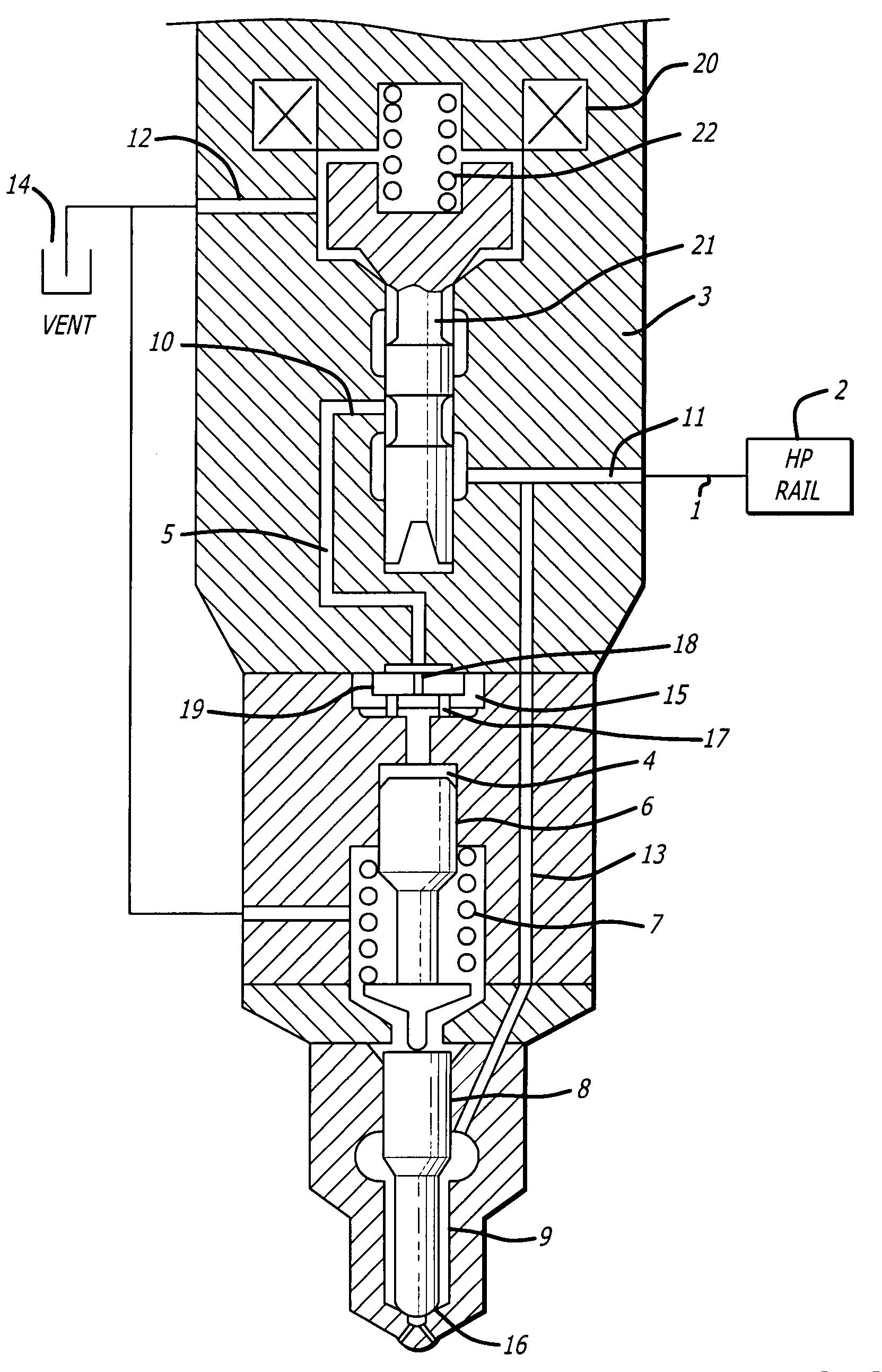
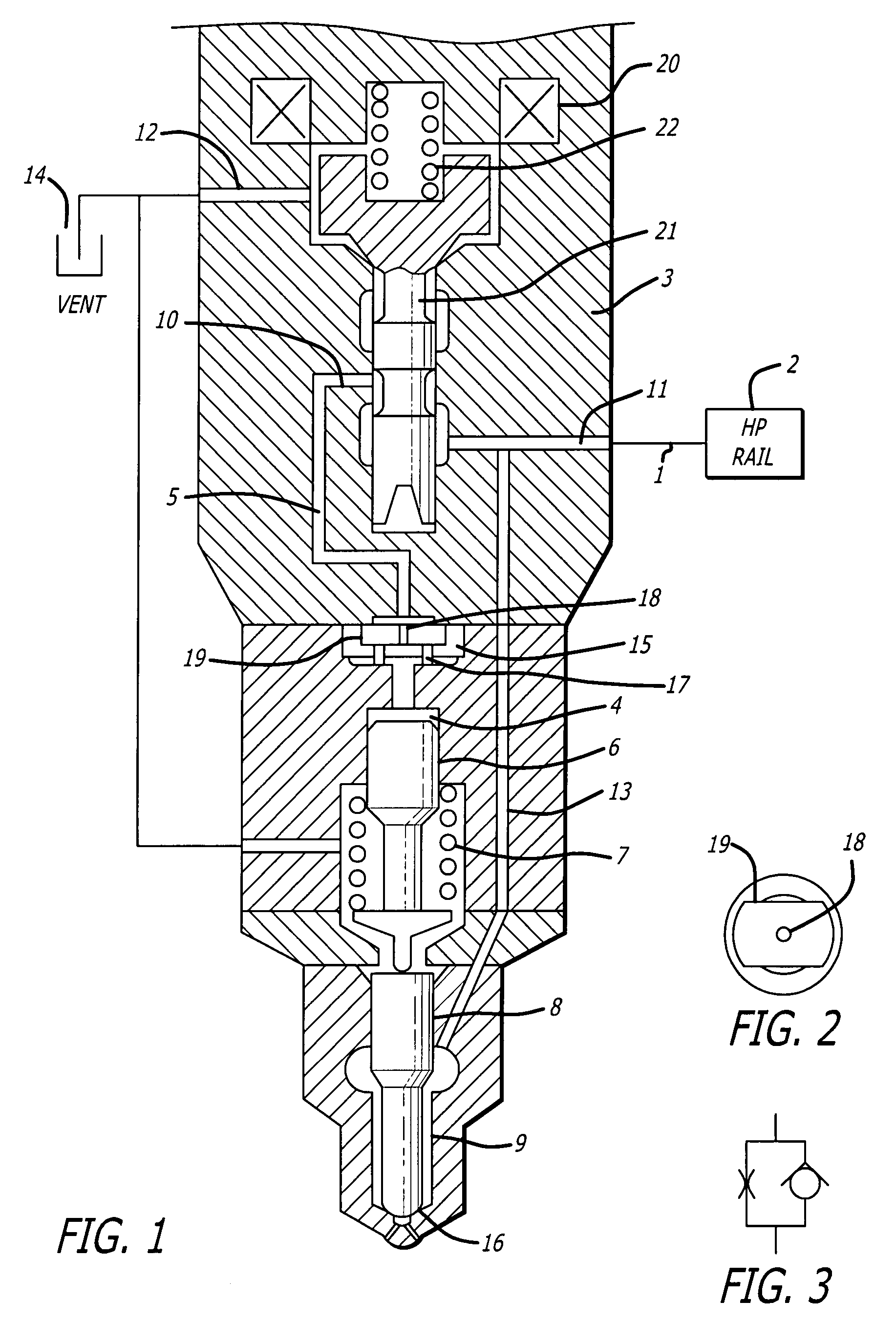
[0011]Diesel injectors with independent control of needle valve opening and closing velocity with a simple low cost design are disclosed.

[0012]As shown in FIG. 1, the main components of the new injectors are a high pressure fuel supply reservoir 2, an electromagnetically actuated 3-way control valve 3, a needle control volume 4, a needle pin 6, a needle spring 7, a needle 8, a fuel volume around the needle 9, a vent volume 14. essentially at ambient pressure, and a check disk 15. A hydraulic line 13 connects the reservoir 2 with the fuel volume 9 around the needle 8. The needle control valve has 3 ports. The supply port 11 is connected to the supply reservoir 2 through hydraulic line 1, the control port 10 is connected to the needle control volume 4 through a hydraulic line 5 and the check disk 15, and the vent port 12 is connected to the vent 14. The needle control valve has a supply and a vent position, and is normally (when not energized) in the supply position as shown. In the s...


PUM


Abstract

Direct needle control fuel injectors and methods disclosed. The preferred embodiment injectors have a needle within a needle chamber for movement between a closed position preventing injection of fuel and an open position allowing injection of fuel, a source of high pressure fuel coupled to the needle chamber to provide fuel for injection and to hydraulically urge the needle to the open position by pressurizing a first hydraulic area associated with the needle, a needle control hydraulic area having a second hydraulic area disposed to urge the needle to the closed position when the second hydraulic area is exposed to fuel under pressure, and valving coupled to the source of high pressure fuel and a vent to controllably couple the hydraulic area of the needle control member to the high pressure fuel or to the vent.

Description

CROSS-REFERENCE TO RELATED APPLICATION[0001]This application claims the benefit of U.S. Provisional Patent Application Ser. No. 60 / 782,030 filed Mar. 13, 2006.BACKGROUND OF THE INVENTION[0002]1. Field of the Invention[0003]The present invention relates to the field of fuel injectors.[0004]2. Prior Art[0005]Conventional 2-way needle control valves to control the motion of a diesel injector's needle valve have been in use for quite some years. They provide acceptable but not superior controllability with relatively low cost. On the other hand, needle control with 3-way valves has not been commercialized to the same extent. They provide superior flexibility in controlling the needle motion, but with relatively higher cost.[0006]Direct needle control with 2-way valves is relatively simpler and lower cost. However, the flexibility in controlling the needle motion during both opening and closing through the entire pressure range is not optimal.[0007]Previous direct needle control injector...

Claims


Application Information

Patent Timeline
Patent Type & Authority Patents(United States)
IPC IPC(8): F02M59/46F02M59/44
CPCF02M47/027F02M63/0015F02M63/0045F02M63/0054F02M63/004F02M57/02F02M61/205F02M2547/006F02M63/0225F02M2200/28
Inventor PENA, JAMES A.KISS, TIBOR
Owner STURMAN INDS
Why Eureka
Try Eureka