Downhole tool

a tool and tool body technology, applied in the field of selective operation of downhole tools, can solve the problems of affecting etc., and achieves the effect of saving significant time in the operation of the well, reducing the risk of shock, and reducing the service life of the tool

Active Publication Date: 2008-08-26
SCHLUMBERGER OILFIELD UK LTD
View PDF18 Cites 157 Cited by
  • Summary
  • Abstract
  • Description
  • Claims
  • Application Information

AI Technical Summary

Benefits of technology

[0014]According to a first aspect of the present invention there is provided a downhole tool for selectively performing a task in a well bore, the tool comprising a substantially cylindrical body having a central bore running axially therethrough, a sleeve located within the bore, the sleeve including a ball seat, a plurality of balls, each ball having substantially similar dimensions and each ball arresting a majority of fluid flow through the bore when located in the ball seat, mechanical biasing means located between the sleeve and the body to bias the sleeve in a first direction, and functional means on the body to perform a task in the well bore, the functional means being operable on relative movement of the sleeve, wherein the functional means has at least a first and a second operating position, each change in position being effected by passing a said ball through the sleeve in a reverse direction, and wherein the said changes form a cyclic pattern such that the functional means can be cycled back to the first operating position.
[0015]The tool can therefore be operated a number of times while located in a well bore. Further all operations are controlled by dropping identical balls through the tool and thus there is no co-ordination required in dropping the balls.

Problems solved by technology

This saves significant time in making the well operational.
The tools are generally limited to one actuable movement.
If two sleeves are incorporated to overcome this, the shear screws of the second sleeve can operate prematurely under the shock created to shear the shear screws of the first sleeve.
Additionally, the reduced bore diameter of the lower part also effects the flow rate achievable through the tool.
A disadvantage of this tool is that it requires both a deformable ball and a smaller metal ball to operate.
This limits the amount of cleaning which can be performed.

Method used


Image

  • Downhole tool
  • Downhole tool
  • Downhole tool

Examples


Embodiment Construction

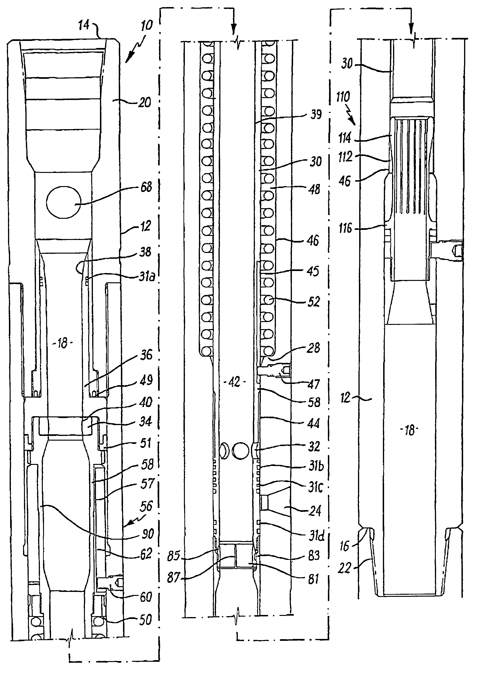
[0085]Reference is initially made to FIG. 1 of the drawings which illustrates a downhole tool, generally indicated by reference numeral 10, in accordance with an embodiment of the present invention. Tool 10 includes a cylindrical body 12 having an upper end 14, a lower end 16 and a cylindrical bore 18 running therethrough. The body 12 has a box section 20 located at the upper end 14 and a pin section 22 located at the lower end 16 for connecting the tool 10 in a work string or drill string (not shown).

[0086]The body 12 further includes five radial ports 24 located equidistantly around the body 12. The ports 24 are perpendicular to the bore 18.

[0087]Within the bore 18 there is located a sleeve 30. Sleeve 30 is an annular body which includes five radial ports 32 located equidistantly around the sleeve 30. The ports 32 are perpendicular to the bore 18. The ports 32 are of a similar size to the ports 24 in the body 12.

[0088]On an outer surface 44 of the sleeve 30 there is located a long...


PUM


Abstract

A downhole tool which can perform a task in a well bore, such as circulating fluid radially from the tool. The function is selectively performed by virtue of a sleeve moving within a central bore of the tool. Movement of the sleeve is effected by dropping a ball through a ball seat on the sleeve. Movement of the sleeve is controlled by an index sleeve such that the tool can be cycled back to the first operating position by dropping identical balls through the sleeve. Embodiments are described wherein the balls are deformable, the seat is deformable and the seat provides a helical channel through which the ball passes.

Description

CROSS-REFERENCE TO RELATED APPLICATIONS[0001]This application claims priority form PCT / GB04 / 001449, having an international filing date of 31 Mar. 2004, and a priority date of 1 Apr. 2003 (from GB0307521.5), 3 Apr. 2003 (from GB0307724.1), 4 Apr. 2003 (from GB0307825.0), and 8 Apr. 2003 (from GB0308080.1).STATEMENT REGARDING FEDERALLY SPONSORED RESEARCH OR DEVELOPMENT[0002]Not ApplicableTHE NAMES OF THE PARTIES TO A JOINT RESEARCH AGREEMENT[0003]Not ApplicableINCORPORATION-BY-REFERENCE OF MATERIAL SUBMITTED ON A COMPACT DISC[0004]Not ApplicableBACKGROUND OF THE INVENTION[0005]The present invention relates to the selective operation of downhole tools as used in the oil and gas industry and in particular, though not exclusively, to a re-settable circulation tool operated by a drop ball mechanism.[0006]While many downhole tools operate continuously through a well bore e.g. scrapers and brushes as disclosed in U.S. Pat. No. 6,227,291, it is more desirable to provide a tool which perform...

Claims


Application Information

Patent Timeline
Patent Type & Authority Patents(United States)
IPC IPC(8): E21B34/00E21B23/00E21B34/14
CPCE21B21/103E21B34/14E21B23/006E21B2034/007E21B2200/06E21B23/004E21B34/142
Inventor TELFER, GEORGESCOTT, EDWARD DOCHERTYYOUNGOR, RAE ANDREWATKINS, JAMES EDWARD
Owner SCHLUMBERGER OILFIELD UK LTD
Why Eureka
Try Eureka