Support member for a seating structure

a support member and seating technology, applied in the field of tilt control mechanisms, can solve the problems of uncomfortable pulling of the user's shirt, the inability of the armrest to provide such capabilities in combination, and the mechanism used to adjust the load on the spring(s) or the load capability of the spring(s), etc., to achieve the effect of improving the tilt control mechanism, easy and simple adjustment, and quick installation

Inactive Publication Date: 2008-09-02
MILLERKNOLL INC
View PDF97 Cites 150 Cited by
  • Summary
  • Abstract
  • Description
  • Claims
  • Application Information

AI Technical Summary

Benefits of technology

This patent describes new improvements to tilt chairs and seating structures. These include better resistance control, easy installation, synchronized back and seat tilting, reduced weight, customizable appearance options, and more efficient production methods. Other technical advancements include a modular tilt housing for multiple seating configurations, interchangeable parts, and flexible actuation mechanisms. There are also innovations in armrests, seat depth adjustments, and tilt limits. Overall, these developments enhance the performance and versatility of tilt chairs and make them easier to produce and modify.

Problems solved by technology

The present invention is about a new type of tiltable chair that has a flexible back, adjustable armrests, and an adjustable seat depth. The problem that this invention solves is that traditional chairs have limitations in their movement and can cause discomfort or limitations in the user's range of motion. Additionally, previous chairs have complicated mechanisms and are difficult to assemble and adjust. The invention provides a solution that allows for more synchronized and comfortable movement, as well as easy adjustments for different users and situations.

Method used


Image

  • Support member for a seating structure
  • Support member for a seating structure
  • Support member for a seating structure

Examples


first embodiment

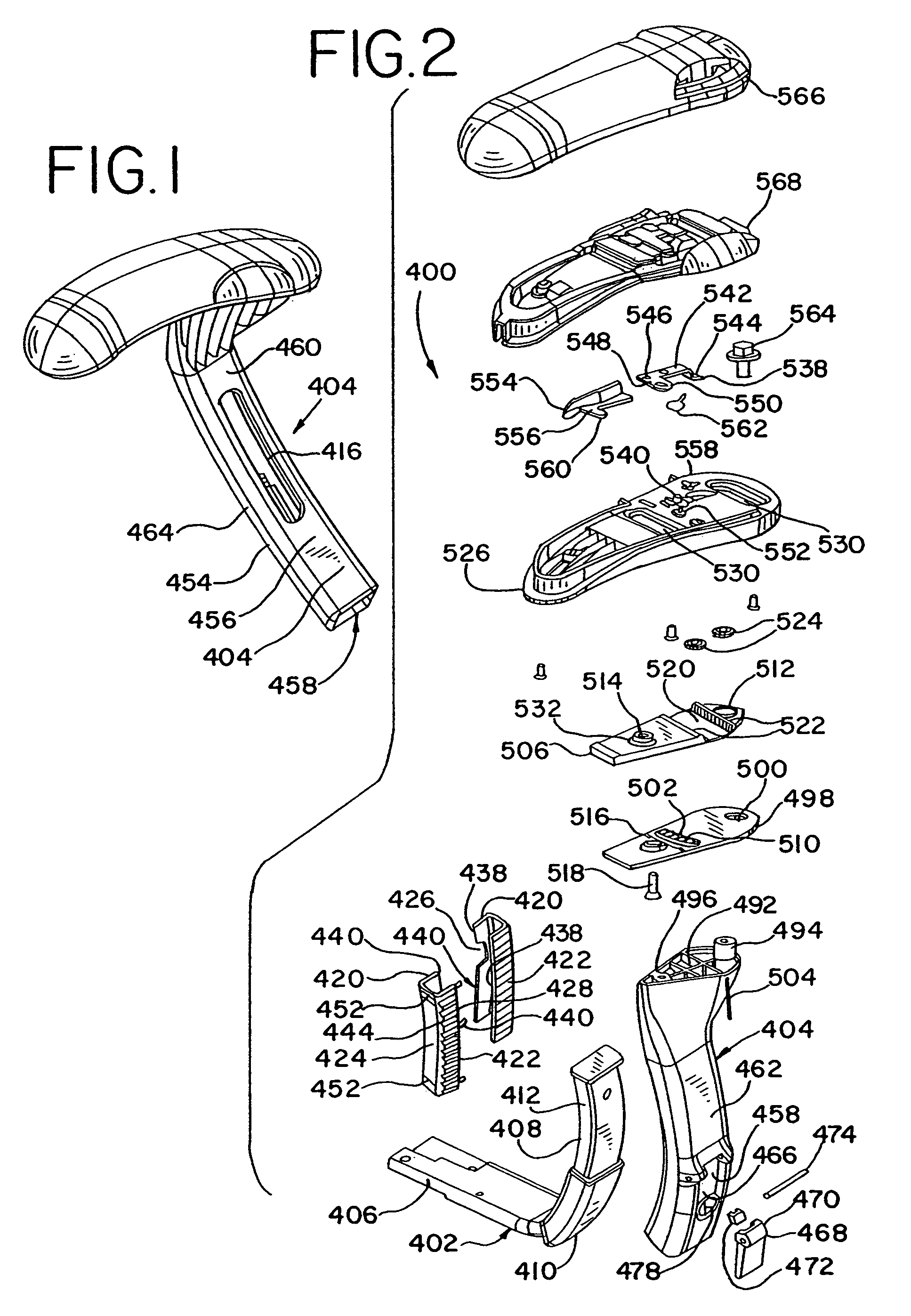
[0173]In the platform 506, shown in FIG. 2, the platform includes a recess or channel 520 formed across an entire width thereof. A pair of spaced apart and parallel linear gears 522, or racks, define the opposite side walls of the channel. An armrest support 526, shown in FIGS. 2 and 7, includes a pair of axles 528 that define a pair of spaced apart axes of rotation. A pair of pinion gears 524 are mounted to the armrest support on the axles 528 and are disposed in the channel 520, such that each of the pinion gears mesh with each other and one of the linear gears 522 respectively.

second embodiment

[0174]In a second embodiment, shown in FIGS. 6, 8 and 84, the platform has only a single linear gear 522, with an opposite wall of the channel 520 being preferably substantially smooth. The armrest support has only a single axle 528 defining an axis of rotation. A single pinion gear 524 is rotatably mounted on the axle 528 within the channel and meshes with the linear gear 522.

[0175]In either embodiment, as shown in FIGS. 2, 6, 8 and 84, the armrest support 526 includes a pair of spaced apart and substantially parallel tracks 530, shown as slots, formed therethrough. One of the tracks 530 receives the guide member 494 extending upwardly from the stem through the platforms 498, 506, while the other receives a guide member 532 formed on an upper surface of the platform 506, and through which the fastener 518 passes to secure the platforms 498, 506. In operation, the user moves the armrest support 526 laterally relative to the platform 506, such that in one preferred embodiment, the pi...


PUM


Abstract

A support member for a seating structure component includes a first support member having a first plurality of spaced apart fins and a second support member having a second plurality of spaced apart fins. The first support member is secured to the second support member with the first plurality of fins nested between the second plurality of fins.

Description


Claims


Application Information

Patent Timeline
Owner MILLERKNOLL INC
Why Eureka
Try Eureka