Treatment and diagnostic catheters with hydrogel electrodes

a technology of hydrogel electrodes and catheters, applied in the field of hydrogel electrode catheters, can solve the problems of large temperature gradients and hot spots, affecting the treatment effect, and forming undesirable coagulum and surface tissue charring,

Inactive Publication Date: 2008-09-02
ST JUDE MEDICAL ATRIAL FIBRILLATION DIV
View PDF59 Cites 87 Cited by
  • Summary
  • Abstract
  • Description
  • Claims
  • Application Information

AI Technical Summary

Problems solved by technology

Several difficulties may be encountered, however, when attempting to form adequately-deep lesions at specific locations using some existing ablation electrodes.
At the edges of some existing electrodes are regions of very high current density, leading to large temperature gradients and hot spots.
These “edge effects” may result in the formation of undesirable coagulum and charring of the surface tissue.
For example, undesirable coagulum may begin to form when blood reaches around 80° C. for an appreciable length of time, and undesirable tissue charring and desiccation may be seen when tissue reaches around 100° C. for an appreciable length of time.
There are two main types of undesirable coagulum: coagulum that adheres to and damages the medical device; and coagulum blood clots or curds that may enter a patient's bloodstream, possibly resulting in other health problems for the patient.
Charring of the surface tissue may also have deleterious effects on a patient.
During RF ablation, as the temperature of the electrode is increased, the contact time required to form an adequately-deep lesion decreases, but the likelihood of charring surface tissue and forming undesirable coagulum increases.
As the temperature of the electrode is decreased, the contact time required to form an adequately-deep lesion increases, but the likelihood of charring surface tissue and forming undesirable coagulum decreases.
Active temperature control may help, but the placement of thermocouples, for example, is tricky and setting the RF generator for a certain temperature becomes an empirical exercise as actual tissue temperatures are generally different from those recorded next to the electrode due to factors such as convection and catheter design.
Since mapping catheters are desirably disposable, incorporation of relatively expensive platinum electrodes may be disadvantageous.
Another difficulty encountered with existing ablation catheters and mapping catheters is how to ensure adequate tissue contact.
All of these devices comprise rigid electrodes that do not always conform to the tissue surface, especially when sharp gradients and undulations are present, such as at the ostium of the pulmonary vein in the left atrium and the isthmus of the right atrium.
Consequently, continuous linear lesions are difficult to achieve.
Whether forming lesions or mapping in a heart, the beating of the heart, especially if erratic or irregular, further complicates matters, making it difficult to keep adequate contact between electrodes and tissue for a sufficient length of time.
For example, with a rigid electrode, it can be quite difficult to maintain sufficient contact pressure during lesion formation until an adequate lesion has been formed.
These problems are exacerbated on contoured or trabeculated surfaces.
If the contact between electrodes and tissue cannot be properly maintained, quality lesions or accurate mapping are unlikely to result.
Catheters based upon a virtual electrode that deliver RF energy via conductive fluid flowing into the patient's body address some of the difficulties with ablation catheters, but these ablation catheters often require high flow rates of the conductive fluid (e.g., typically around 70 milliliters per minute) to maintain effective cooling for high-power RF applications.
The introduction of a large amount of conductive fluid into a patient's bloodstream may have detrimental effects on the patient.

Method used


Image

  • Treatment and diagnostic catheters with hydrogel electrodes
  • Treatment and diagnostic catheters with hydrogel electrodes
  • Treatment and diagnostic catheters with hydrogel electrodes

Examples


first embodiment

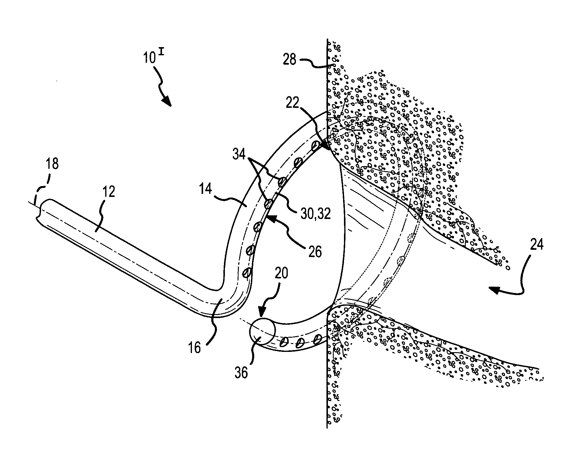
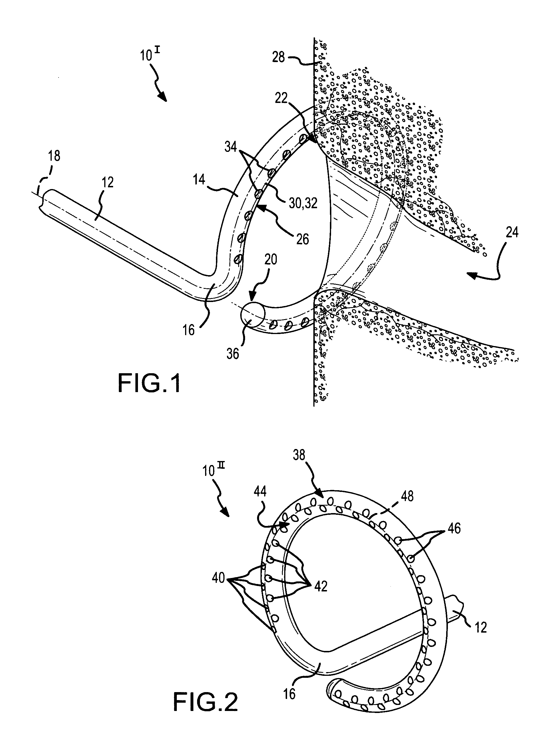
[0045]FIG. 1 is a fragmentary, isometric view of the distal portion 10I of an ablation catheter according to the present invention. In this embodiment, the distal portion 10I of the ablation catheter comprises a straight section 12 and a curved or hoop-shaped section 14 that are joined at a bend or offset 16. A longitudinal axis 18 extends through both the straight section 12 and the curved section 14. As used herein, the term “longitudinal axis” refers to the longitudinal axis extending through the straight section 12 and through the curved section 14 of the ablation catheter, from the proximal end (not shown) of the catheter to the distal end 20 of the ablation catheter. The curved or hoop-shaped section 14 is C-shaped as shown, but may define a completely circular configuration rather than the open, C-shape depicted in FIG. 1. The bend or offset 16 may be formed or configured as shown in FIG. 1, wherein the offset displaces the straight section 12 of the catheter to the side, cau...

fourth embodiment

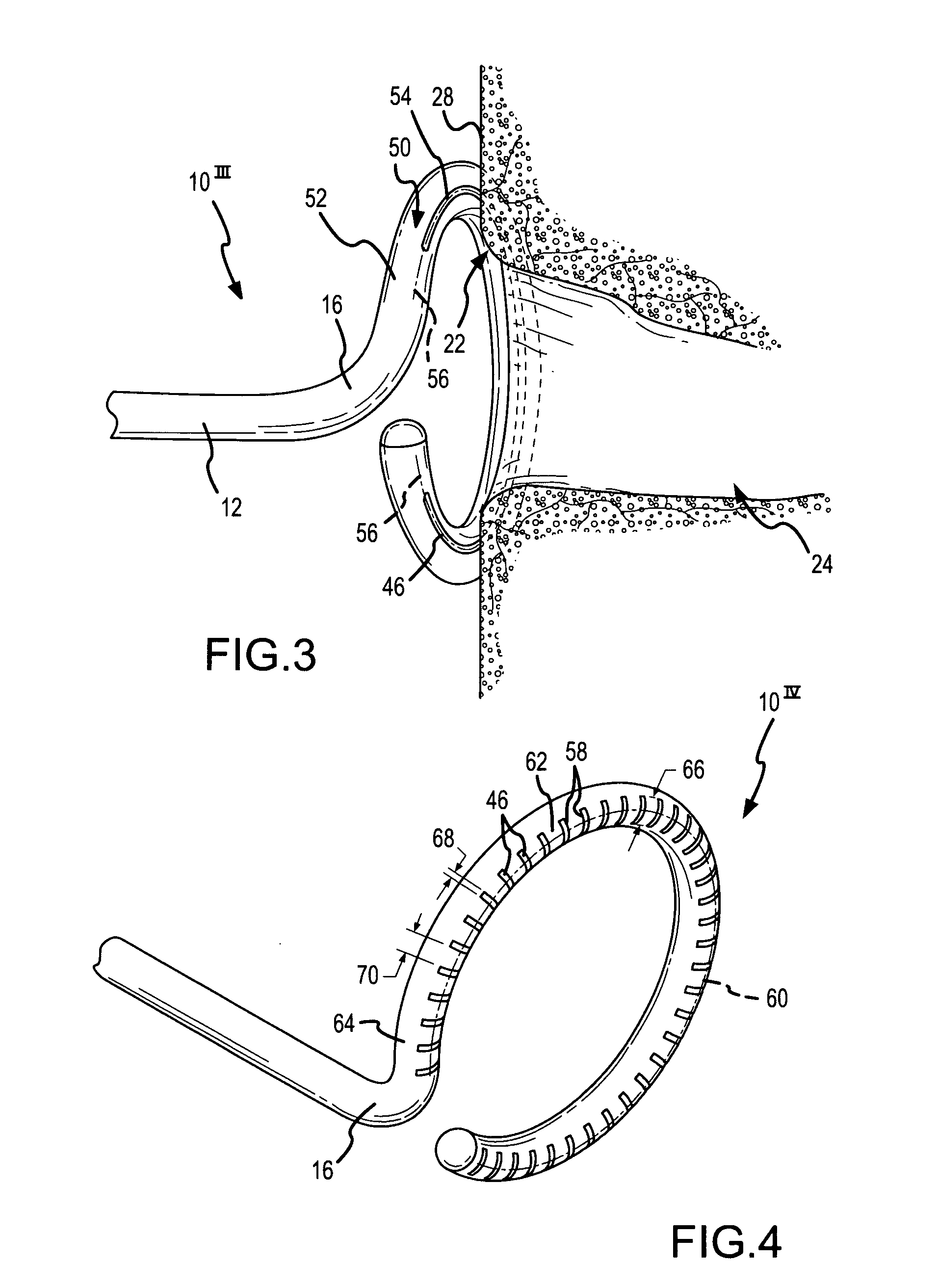
[0050]FIG. 4 is a fragmentary, isometric view of the distal portion 10IV of an ablation catheter according to the present invention. The embodiment depicted in FIG. 4 is similar to the embodiments depicted in FIGS. 1-3, except for the hydrogel deployment feature. In FIG. 4, the conductive hydrogel 46 is deployed or delivered through the catheter and against the tissue 28 being ablated via a plurality of laterally-extending or transversely-extending hydrogel slots 58. These laterally-extending hydrogel slots 58 extend substantially perpendicularly to the arc or line defining a slot centerline 60 along the radial apex of the distally-facing surface 62 of the curved section 64 of the ablation catheter. The transverse length 66 of each hydrogel slot 58 may be adjusted to obtain the desired lesion width. The longitudinal width 68 of each hydrogel slot 58 as well as the separation distance 70 between adjacent slots may be adjusted to control potential gaps in the arcuate lesion formed dur...

fifth embodiment

[0051]FIGS. 5-7 are fragmentary views of the distal portion 10V of an ablation catheter according to the present invention. In the embodiment depicted in FIGS. 5-7, the hydrogel deployment feature comprises a plurality of hydrogel portholes 72 arranged along a single row, similar to the plurality of portholes 34 depicted in FIG. 1. In the embodiment of FIGS. 5-7, however, the single row of hydrogel portholes 72 is present along a porthole centerline 74 on the radial apex of an outer peripheral wall 76 of the curved section 78 rather than being on the radial apex 30 of the distally-facing surface 26 as shown in FIG. 1. In other words, the ablation catheter depicted in FIGS. 5-7 comprises an inner peripheral wall 80 and an outer peripheral wall 76 on the hoop-shaped or curved section 78, and the portholes 72 extend substantially radially through the outer peripheral wall 76 of this C-shaped or hoop-shaped curved section 78 of the ablation catheter.

[0052]FIG. 6 is a fragmentary, end vi...


PUM


Abstract

Straight and curved catheters for treatment or diagnoses of tissue, including cardiac tissue, using hydrogel virtual electrodes and hydrogel sensing electrodes are disclosed. Each catheter comprises at least one conductive hydrogel electrode, whether a virtual electrode or a sensing electrode. Hydrogel virtual electrodes may be used to deliver ablative energy or chemotherapeutic agents to tissue. Hydrogel sensing electrodes may be used to map various electrical activity of tissue. The ablation catheters include a variety of hydrogel delivery features to deliver the conductive hydrogel electrodes against or adjacent to tissue to be treated. Each hydrogel delivery feature comprises at least one opening in the distal portion of the catheter and may also include a permeable or semi-permeable membrane. The mapping catheters include conductive hydrogel disks (i.e., conductive hydrogel sensing electrodes) and nonconductive hydrogel disks. Methods of treating and diagnosing tissue using hydrogel virtual electrodes and hydrogel sensing electrodes are also disclosed.

Description

BACKGROUND OF THE INVENTION[0001]a. Field of the Invention[0002]The instant invention is directed toward hydrogel electrode catheters for treatment and diagnosis of tissue. More specifically, the instant invention relates to treatment and diagnostic catheters with hydrogel virtual and sensing electrodes.[0003]b. Background Art[0004]Catheters have been in use for medical procedures for many years. Catheters can be used for medical procedures to examine, diagnose, and treat tissue while positioned at a specific location within the body that is otherwise inaccessible without more invasive procedures (e.g., medical procedures involving the human heart). During these procedures a catheter is inserted into a vessel located near the surface of a human body (e.g., an artery or vein in the leg, neck, or arm of the patient) and is guided or threaded through the vessels, sometimes with the aid of a guidewire or introducer, to a specific location within the body for examination, diagnosis, and ...

Claims


Application Information

Patent Timeline
Patent Type & Authority Patents(United States)
IPC IPC(8): A61B18/14A61B5/296
CPCA61B18/1492A61B2018/1472A61B2018/00375
Inventor KAMPA, GREGORY J.
Owner ST JUDE MEDICAL ATRIAL FIBRILLATION DIV
Why Eureka
Try Eureka