Integral spine structure for footwear

a spine structure and footwear technology, applied in the field of footwear, can solve the problems of unstable footwear, unstable footwear, and instability

Inactive Publication Date: 2008-09-09
RED WING SHOE
View PDF35 Cites 107 Cited by
  • Summary
  • Abstract
  • Description
  • Claims
  • Application Information

AI Technical Summary

Problems solved by technology

For example, a footwear with a very thick sole that raises an individual's center of gravity beyond a natural position may provide a very unstable scenario.
Further, some types of materials used in footwear are very flexible and if used alone without any other support features may create an unstable footwear.
Some types of material that do not allow flexibility may effect the natural motion of the foot and further create instability.
For example, undue amounts of torsional flexibility about a transverse axis of the footwear in the area of the arch of the foot may result in inadequate guiding and holding of the foot if the footwear bottom also provides too much longitudinal flexibility in that region of the footwear.
Although the plate structure may distribute pressure, the heel strike and other significant shock forces are not dissipated very well.
Furthermore, because there is no support structure in the forefoot of the footwear, the footwear may be entirely too flexible for a given application and fails to provide the torsional rigidity that is necessary for support and stability of the footwear.
This type of design is difficult to alter for the support, stability and shock attenuation needs of different applications while concurrently providing necessary flexibility along the length of the footwear.
Some footwear designs may include materials or structures that are not conducive to cost effective manufacturing and assembly of the footwear.

Method used


Image

  • Integral spine structure for footwear
  • Integral spine structure for footwear
  • Integral spine structure for footwear

Examples


Embodiment Construction

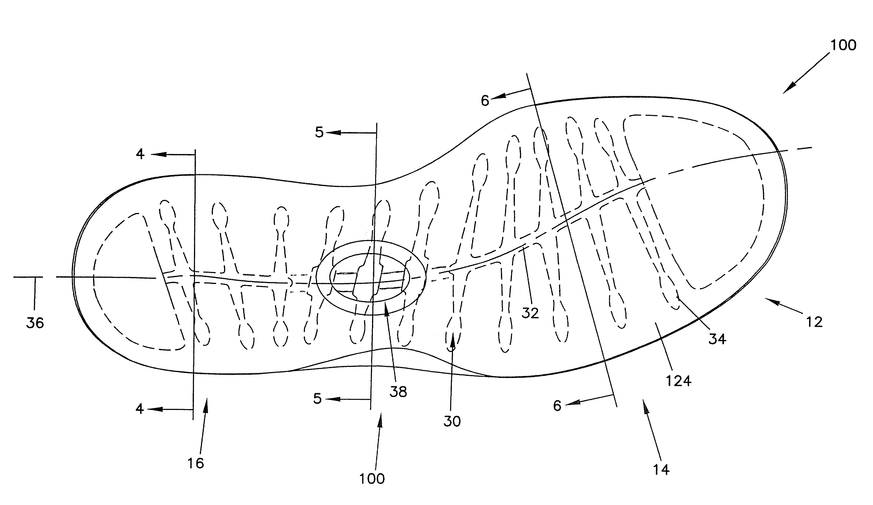
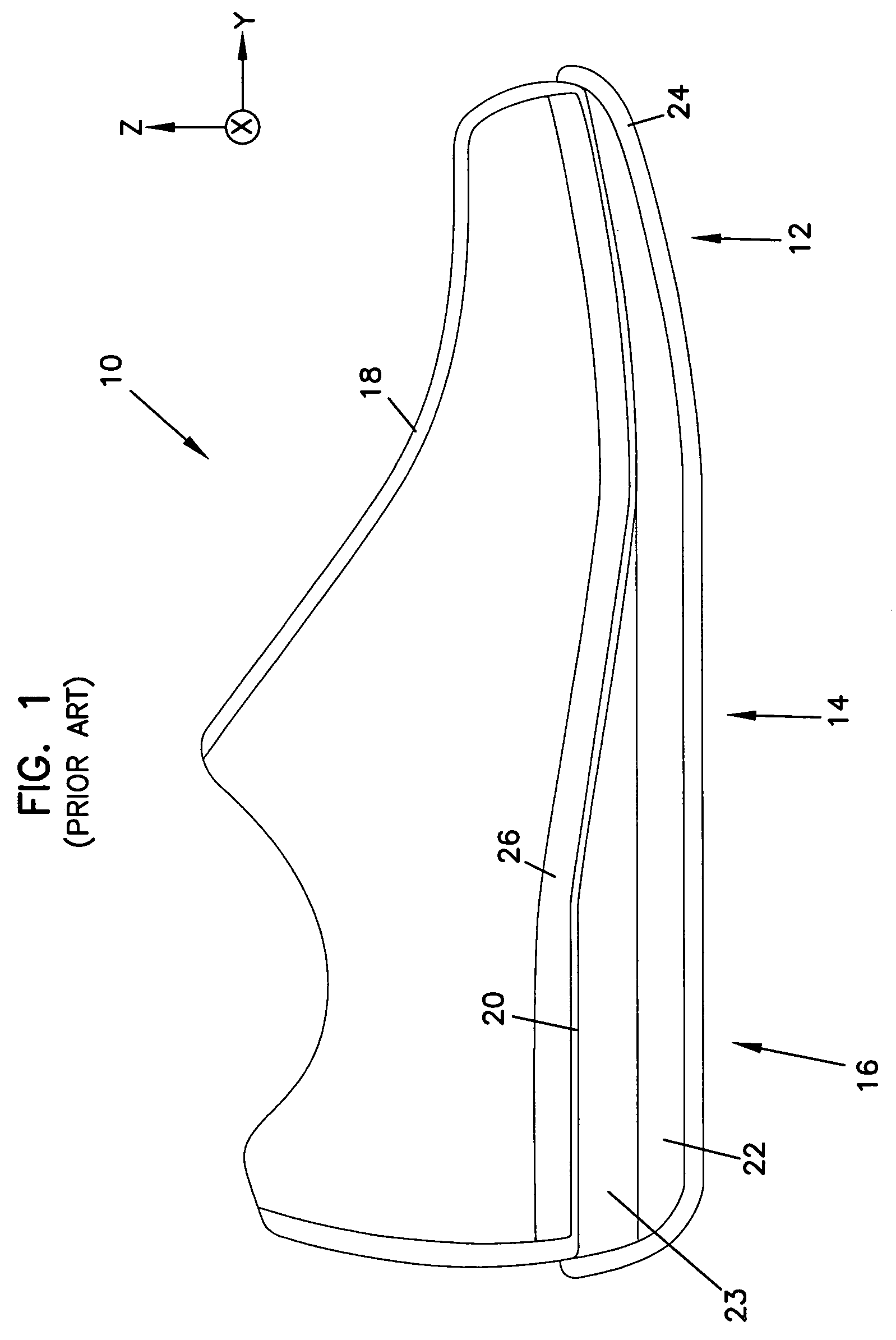
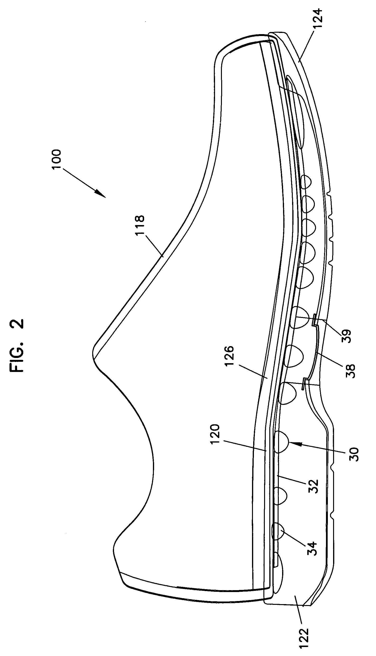
[0103]The present invention generally relates to a support structure for footwear. The support structure includes a longitudinally extending member to which a plurality of laterally extending supports members are secured at spaced apart locations along a length of the longitudinal member. The support structure may extend along the entire length of a footwear or may be specifically designed for the forefoot, midfoot, or hindfoot areas of a footwear. The support structure may be combined with plate-like structures or may include a plurality of longitudinally extending members. The lateral supports may extend in a generally horizontal plane or may extend in an upward or downward direction, or combination of upward, downward, horizontal or generally curved upward or downward directions. Furthermore, the longitudinal and lateral members may be made of different materials, or each may be made of a plurality of different materials to provide the desired characteristics of the support struc...


PUM

PropertyMeasurementUnit
widthaaaaaaaaaa
lengthaaaaaaaaaa
compressibleaaaaaaaaaa

Abstract

A support structure for footwear includes a longitudinally extending member to which a plurality of laterally extending supports members are secured at spaced apart locations along a length of the longitudinal member. The support structure may extend along the entire length of a footwear or may be specifically designed for the forefoot, midfoot, or hindfoot areas of a footwear. The support structure may be combined with plate-like structures or may include a plurality of longitudinally extending members. The lateral supports may extend in a generally horizontal plane or may extend in an upward or downward direction out of the horizontal plane. Furthermore, the longitudinal and lateral members may be made of different materials, or each may be made of a plurality of different materials to provide the desired characteristics of the support structure at a given location in the footwear. Different portions of the longitudinal member may be more or less flexible than the lateral supports.

Description

CROSS REFERENCE TO RELATED APPLICATIONS[0001]This application claims priority to U.S. Provisional Application Ser. No. 60 / 488,476 filed on Jul. 17, 2003, and entitled INTEGRAL SPINE STRUCTURE FOR FOOTWEAR, the disclosure of which is incorporated herein by reference in its entirety.BACKGROUND OF THE INVENTION[0002]1. Technical Field[0003]The present invention generally relates to footwear, and more specifically relates to structures for supporting a footwear.[0004]2. Related Art[0005]A common objective for most types of footwear designs is to address at least one of the following three biomechanical issues: shock attenuation, stability, and support. Shock attenuation involves the absorption of shock, shock diffusion and pressure distribution. The ability of a footwear to attenuate shock forces can greatly reduce the pain and discomfort to a user of the footwear for any given application. Shock absorption may be addressed by the type of materials that are used in the footwear. Various...

Claims


Application Information

Patent Timeline
Patent Type & Authority Patents(United States)
IPC IPC(8): A43B13/00A43B23/00A43B7/14A43B13/12A43B13/14A43B13/18A43B13/41B29D35/06
CPCA43B3/0036A43B3/0052A43B3/0057A43B7/14A43B13/026A43B13/10B29D35/061A43B13/125A43B13/141A43B13/181A43B13/41A43B23/22A43B13/12
Inventor GEER, KENTON D.
Owner RED WING SHOE
Why Eureka
Try Eureka