System and method for simultaneous capping/de-capping of storage containers in an array

a storage container and array technology, applied in the field of automatic system for simultaneously capping and decapping multiple vials in a tray, can solve the problems of inapplicability and the inability to remove one or more selected vials from the holder

Active Publication Date: 2008-09-09
NEXUS BIOSYSTEMS INC
View PDF21 Cites 28 Cited by
  • Summary
  • Abstract
  • Description
  • Claims
  • Application Information

AI Technical Summary

Benefits of technology

[0011]It is an advantage of the present invention to provide an apparatus and method for the automatic removal and replacement of a plurality of caps into a plurality of storage containers such as vials.
[0012]It is another advantage of the present invention to provide a removable cartridge in an automated capper / de-capper system that allows the system to be used on other trays of vials so that the system need not sit idle until testing is completed on a first array of vials.
[0013]The capper / de-capper system for removing or replacing caps for vials in a fixed array includes a removable cartridge with a plurality of sets of gripper plates corresponding to the number of columns in the array. Each set can have either two or three plates, and each plate has a plurality of gripper arms corresponding to the number of rows in the array. The gripper arms have hooked ends which are oriented in opposite directions in each pair of plates. Relative positioning of the gripper arms, is varied by one or more rotating cams, which cause the gripper arms on one or two plates of each set to move relative to the gripper arms of another plate of the set, varying the combined width and / or relative angle of the gripper arms to manipulate a cap that fits into the end of each vial. The plurality of plate sets and gripper arms allow all vials in the array to be capped or de-capped simultaneously.
[0014]In the illustrative embodiment, the cartridge is dimensioned for handling of 96 vials in an 8×12 array. Cartridges with different dimensions may be provided to accommodate more or fewer vial quantities in different arrays.
[0015]The removable cartridge of the present invention includes a frame surrounding a plurality of sets of elongated plates, each plate set corresponding to either one row or one column of vials in the array. In the illustrative embodiment, 8 pairs of plates are used for the 96 vial container. Each set of plates has a plurality of gripper arms extending downward from the bottom of the plate. The gripper arms are “L”- or “J”-shaped hooks that are dimensioned to fit within the top recess of a cap. In the 96 vial container, each plate will have 12 gripper arms. For a plate pair, two corresponding gripper arms are oriented in opposite directions so that their hooked portions are pointed away from each other. For a three plate set, where two plates move and a third plate is relatively stationary, the hooked portions of the moving plates will generally point away from the hooked portions of the stationary plate.
[0016]Adjacent plate sets are separated from each other by a spacer that corresponds to the spacing between the vials so that, when the cartridge is aligned with the array of vials, there will be a pair of gripper arms positioned over each vial. The spacer is generally cylindrical and is supported in place by two or more rods that extend through openings formed in each of the plates.

Problems solved by technology

This is not practical due to the expense of new caps every time the samples are tested or tying up of the de-capping / re-capping tool while the analysis is performed.
A disadvantage of cap mats is that one or more selected vials may not be removed from the holder after they have been sealed with the cap mat.

Method used


Image

  • System and method for simultaneous capping/de-capping of storage containers in an array
  • System and method for simultaneous capping/de-capping of storage containers in an array
  • System and method for simultaneous capping/de-capping of storage containers in an array

Examples


Embodiment Construction

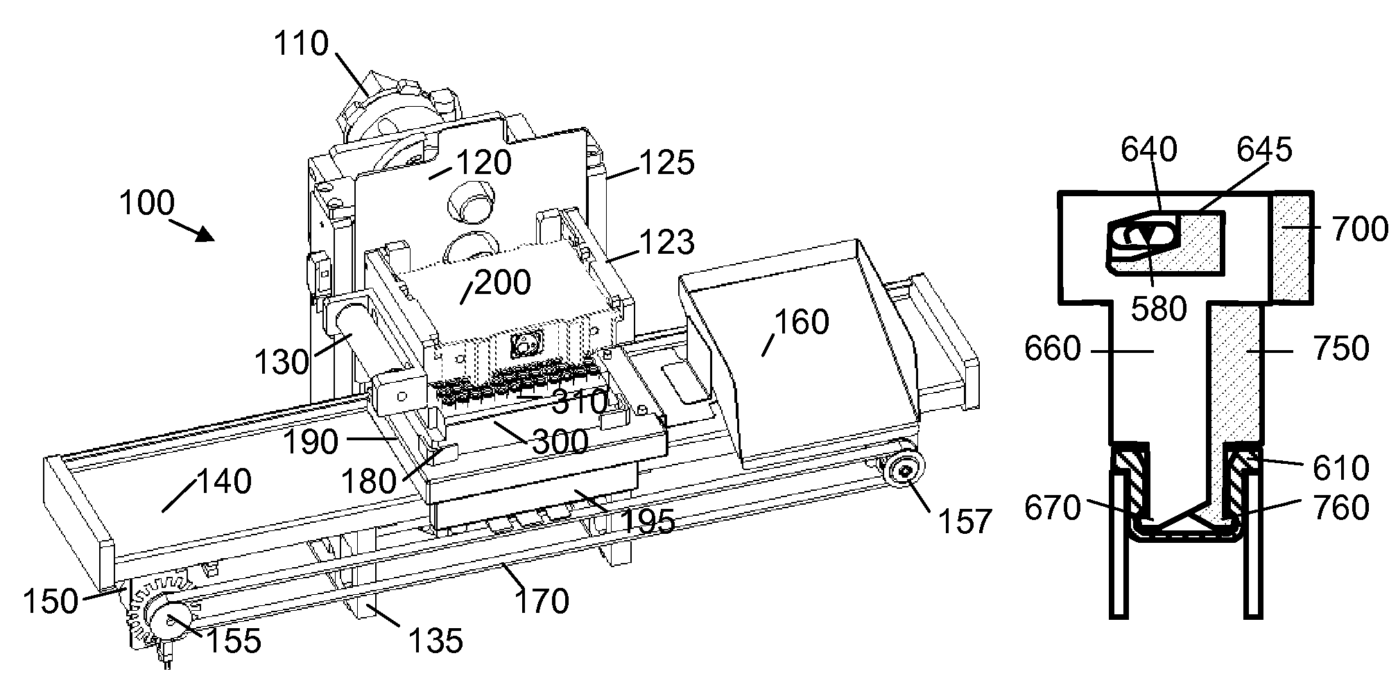
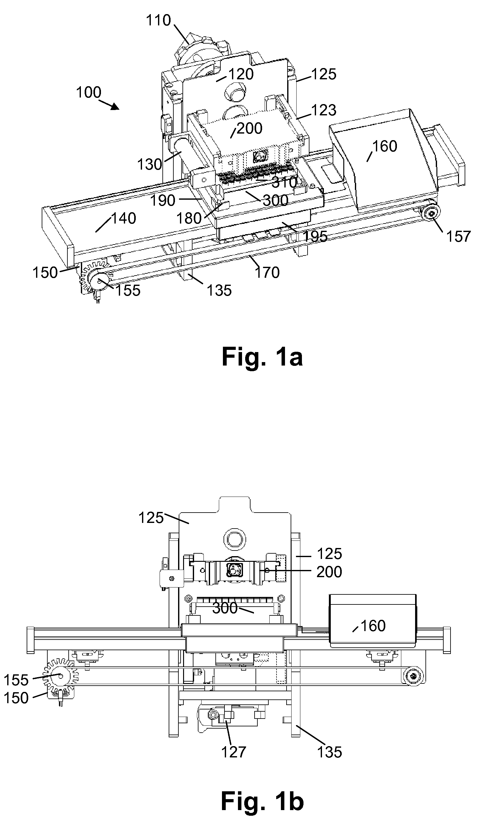
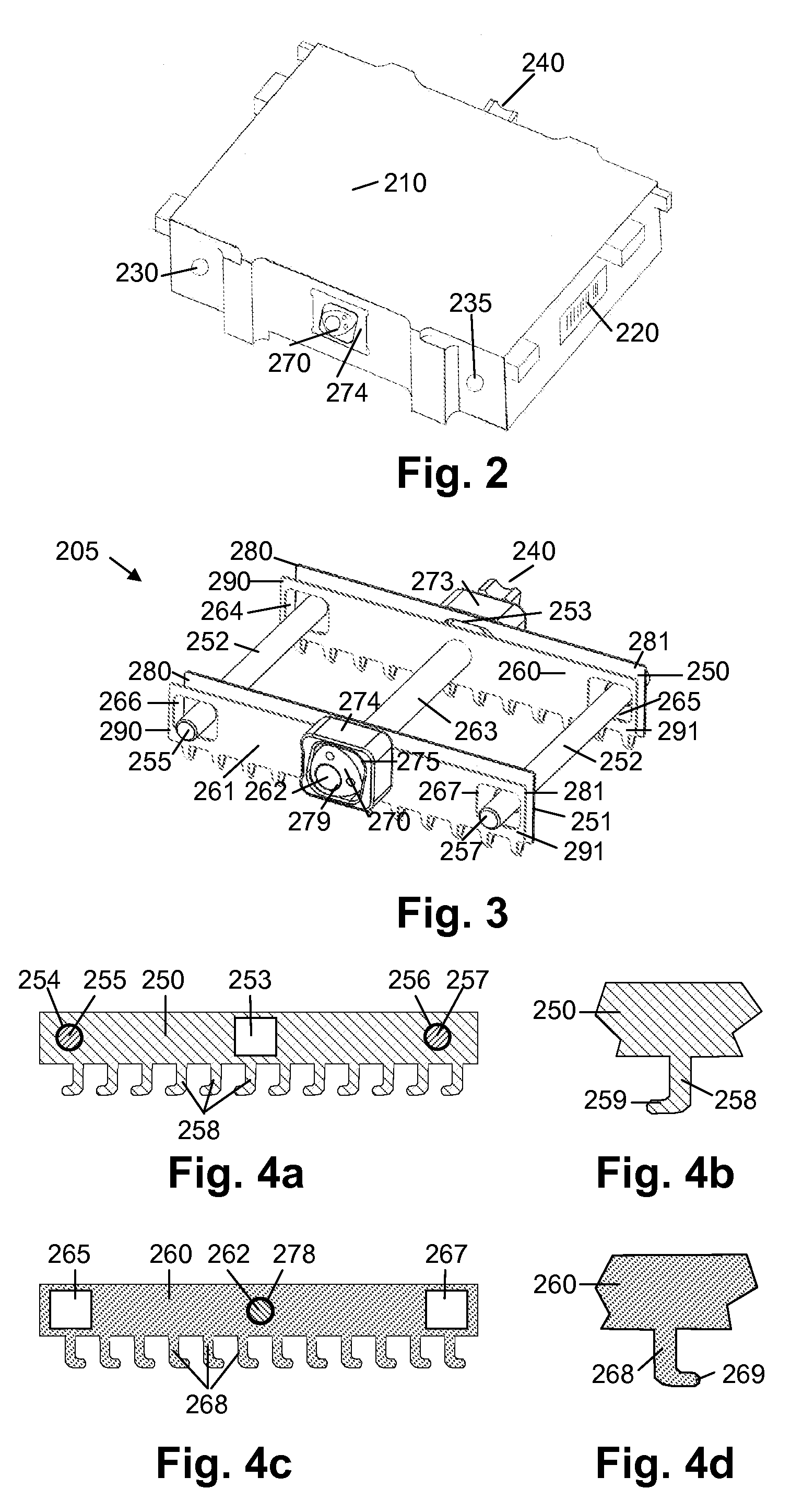
[0030]The present invention relates to an automated system for the capping and de-capping of vials and for the storage of the removed caps such that cross contamination will not easily occur and costs are reduced by enabling reuse of the original caps. The capper / de-capper system includes a cam operator, a removable cartridge that is used to remove, replace, and temporarily store vial caps for an array of vials, a cartridge elevator and a conveyor driver. The system is preferably computer controlled.

[0031]Unless otherwise indicated, the invention is not intended to be limited to any particular materials, dimensions, tray size or number of caps or vials. The use of relative positioning, e.g., up, down, right, left, is not intended to be limiting but is provided for illustrative purposes with reference to the drawings.

[0032]The vial caps to which the present invention is directed are of the type that are inserted into the open upper end of a vial and are retained in place by an interf...


PUM


Abstract

The system for removing or replacing caps for vials in a fixed array includes a removable cartridge with a plurality of sets of gripper plates corresponding to the number of columns in the array. Each plate has a plurality of gripper arms corresponding to the number of rows in the array. The gripper arms have hooked ends which are oriented in opposite directions in each set of plates. Relative positioning of the gripper arms is varied by one or more rotating cams, which cause the gripper arms on one plate of each set to move relative to the gripper arms of the other plate(s) of the set, varying the combined width and / or relative angle of the gripper arms to manipulate a cap inserted into the end of each vial. The plurality of plate sets and gripper arms allow all vials in the array to be capped or de-capped simultaneously.

Description

RELATED APPLICATIONS[0001]This application claims the priority of U.S. Provisional Application No. 60 / 732,032, filed Nov. 1, 2005, which is incorporated herein by reference in its entirety.FIELD OF THE INVENTION[0002]The invention generally relates to a system and method for the removal and installation of caps on a container within an array, and more particularly to an automated system for simultaneously capping and de-capping multiple vials in a tray.BACKGROUND OF THE INVENTION[0003]In the search for new compounds, especially for the pharmaceutical industry, combinatorial methods demand creation and testing of a significant number of compounds.[0004]Using modern techniques and tools, only small aliquots of chemicals are required for testing, therefore small storage containers, such as compound storage vials, can be used to collect and store the chemical compounds. The vials are normally kept in a tray specially designed for the storage and transportation of the vials. The trays co...

Claims


Application Information

Patent Timeline
Patent Type & Authority Patents(United States)
IPC IPC(8): B65B1/04B65B43/20B67B7/62
CPCB65B7/2821B65B7/2835G01N35/028B67B7/02G01N2035/0405B67B1/04
Inventor NEEPER, ROBERT K.BRIDWELL, JOHN
Owner NEXUS BIOSYSTEMS INC
Why Eureka
Try Eureka