Counter balance system and method with one or more mechanical arms

a technology of counter balance system and mechanical arm, which is applied in the direction of mechanical control devices, instruments, gearing, etc., can solve the problems of system not being as user-friendly as desirable, system operation may require substantial energy, etc., and achieve the effect of minimizing the rotational inertia of the arm

Inactive Publication Date: 2008-09-30
DUVAL EUGENE F
View PDF23 Cites 34 Cited by
  • Summary
  • Abstract
  • Description
  • Claims
  • Application Information

AI Technical Summary

Benefits of technology

[0006]Several systems are presented for counterbalancing mechanical arms that have two or more links in series. The joints between the links may have any number of rotational degrees-of-freedom as long as all of the axes of rotation pass through a common point. For each distal link that has any vertical motion of its center-of-gravity, a series of one or more pantograph mechanisms are coupled to the link. The motion of the distal link is reproduced by the pantograph mechan

Problems solved by technology

With such motors, such systems may not be as user friendly as desirable.
In other words, such systems may require

Method used


Image

  • Counter balance system and method with one or more mechanical arms
  • Counter balance system and method with one or more mechanical arms
  • Counter balance system and method with one or more mechanical arms

Examples


Embodiment Construction

Outline of Theory of Operation

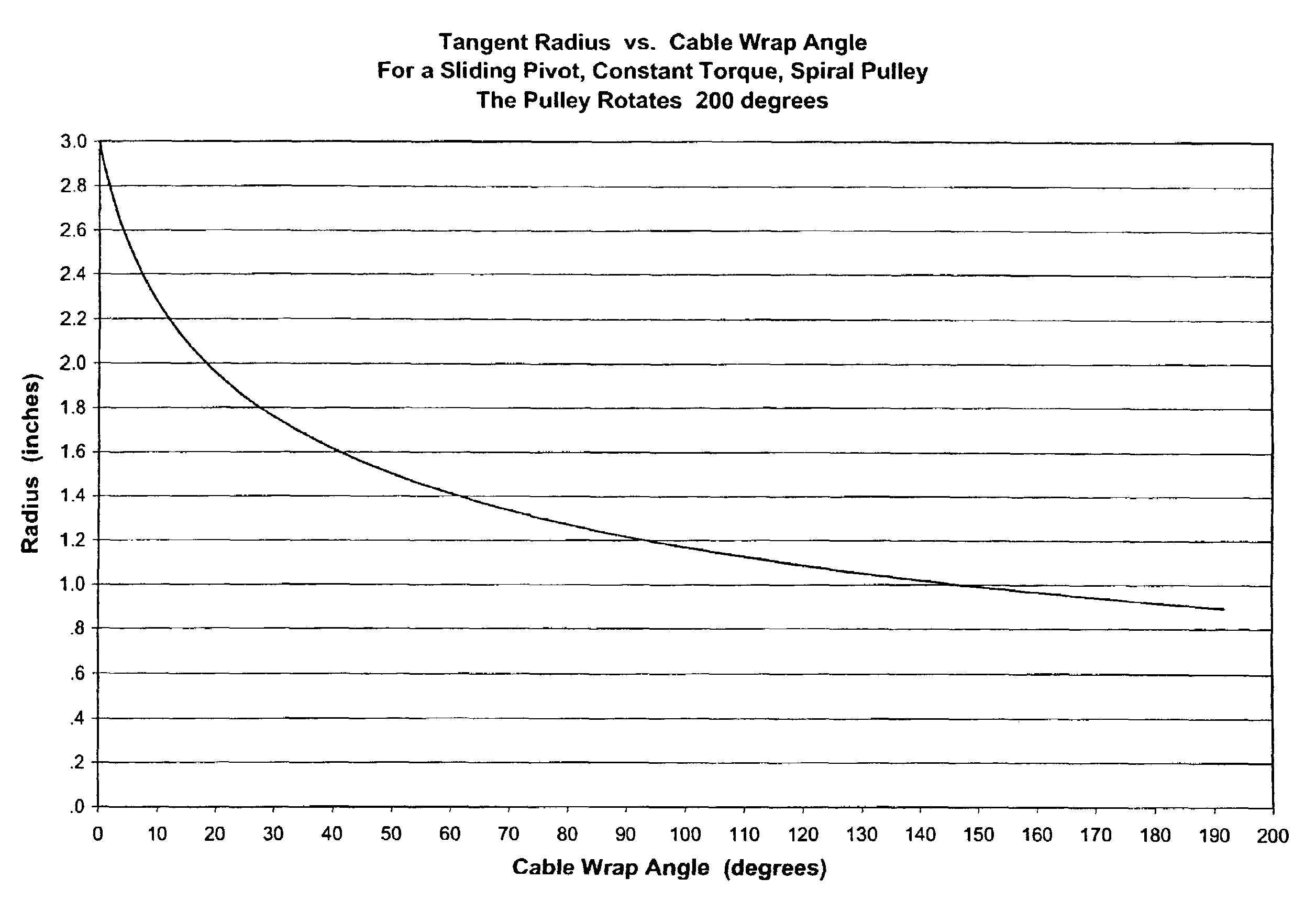
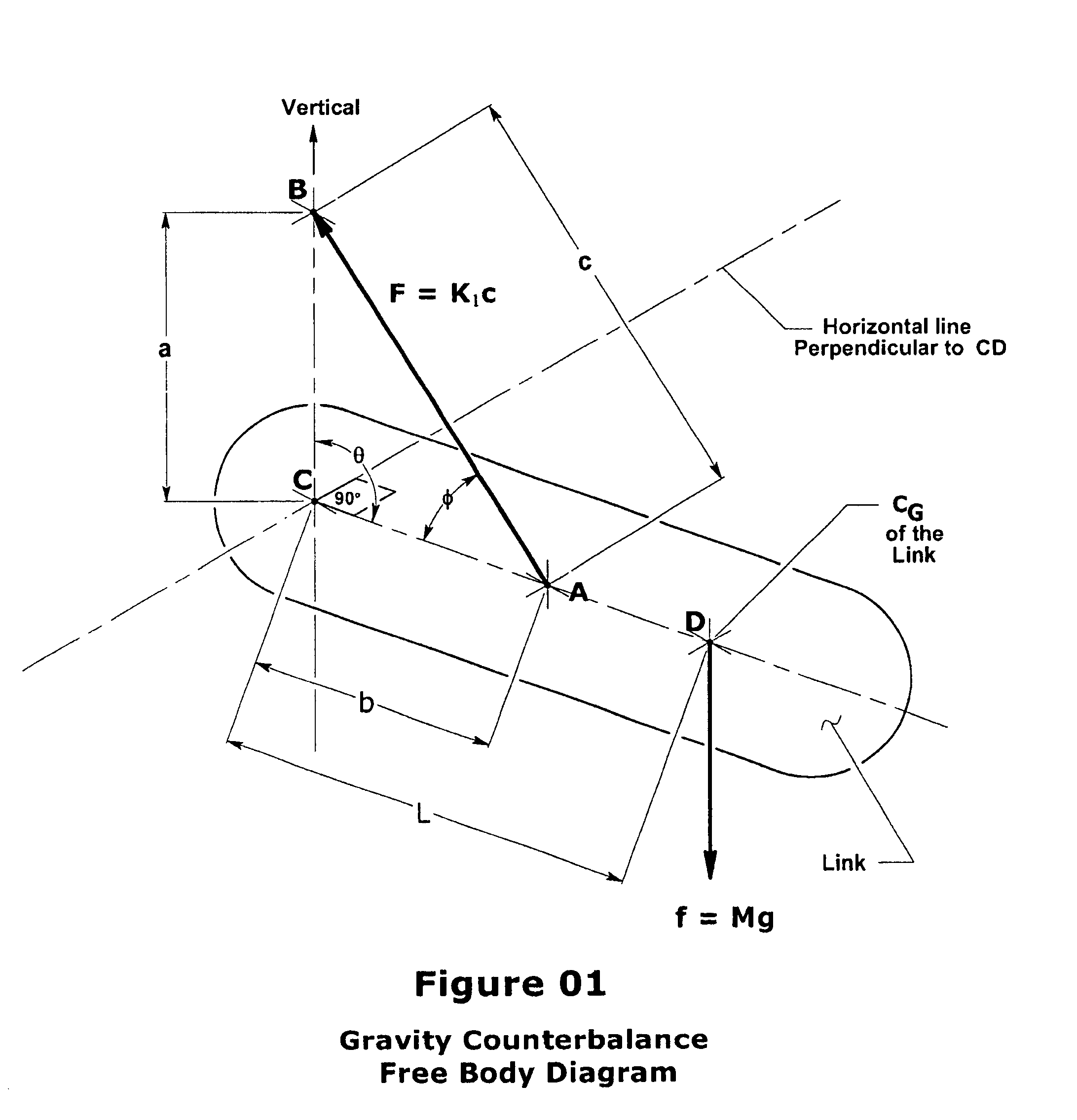
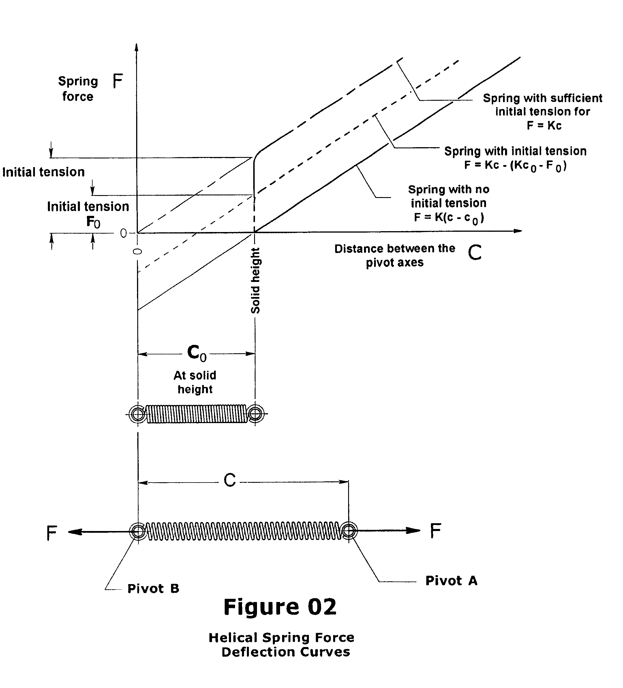
[0067]1. General Case, Rotational Gravity Counterbalance[0068]2. Zero-Length Spring and Cable Gimbal Mechanism[0069]3. Adjustment of the Gravity Counterbalance[0070]Analysis of the force needed to adjust the gravity counterbalance[0071]4. Counterbalancing of the Adjustment Mechanism[0072]The required force profile[0073]Derivation of the geometry for a sliding-pivot spiral pulley[0074]Derivation of the geometry for a fixed-pivot spiral pulley[0075]5. Link-Angle Compensation and Counterbalance Mechanism[0076]Other versions of the link-angle compensation and counterbalance mechanism[0077]6. Load Compensation and Counterbalance Mechanism[0078]7. System Operation[0079]Fixed Gravity Counterbalance[0080]Adjustable Gravity Counterbalance[0081]Gravity Counterbalance with Counterbalanced Adjustment[0082]Gravity Counterbalance with Counterbalanced Adjustment and Link-Angle Compensation[0083]Gravity Counterbalance with Counterbalanced Adjustment and Link-Angle Comp...


PUM


Abstract

A system for counterbalancing the gravitation moment on a link when the link is supported at a point. A first spring mechanism balances the link about all axes that pass through the support point. The link can be balanced throughout a large range of motion.

Description

CROSS REFERENCE TO RELATED APPLICATIONS[0001]This application claims priority to U.S. Provisional Application No. 60 / 382,497, filed May 22, 2002 and U.S. Provisional Application No. 60 / 382,654, filed May 23, 2002, both of which are incorporated herein in their entireties.FIELD OF THE INVENTION[0002]The present invention is directed to mechanical arm systems including one or more mechanical arms.BACKGROUND OF THE INVENTION[0003]There are a number of robotics systems including one or multiple arms which are linked together in order to perform tasks such as lifting and moving objects and tools from one location to another in order to perform these tasks. As the arms and objects and tools have weight, other substantial motors must be used in order to move packages from one location to another. With such motors, such systems may not be as user friendly as desirable. In other words, such systems may require substantial energy in order to operate and will not have as delicate a touch as re...

Claims


Application Information

Patent Timeline
IPC IPC(8): G05G1/00B25J19/00F16F1/12F16H19/00
CPCB25J19/0016F16F1/12Y10T74/2154Y10T74/20329Y10T74/20305Y10T74/20558
Inventor DUVAL, EUGENE F.
Owner DUVAL EUGENE F
Why Eureka
Try Eureka