Image capture apparatus and control method therefor

a technology of image capture and control method, which is applied in the direction of cameras, instruments, printers, etc., can solve the problems of time-consuming and cumbersome, affecting the composition of a subject (a photographic subject) during a user's time, and unable to capture an optimal image. to achieve the effect of easy optimal captur

Inactive Publication Date: 2008-09-30
CANON KK
View PDF18 Cites 34 Cited by
  • Summary
  • Abstract
  • Description
  • Claims
  • Application Information

AI Technical Summary

Problems solved by technology

Thus, even when capturing cannot be performed as intended by a user, e.g., the eyes of a human subject are closed, the subject is in a red-eye state, a luminance degree of a subject's face is too high, or the subject is out of focus, it is difficult for the user to check for such a situation if the displayed subject image is small.
However, magnifying a captured image at each time of capturing takes time and is cumbersome.
Thus, the composition of a subject (a photographic subject) may change during a user's operation even if the user intends to perform capturing again because of incomplete captured images.
In this case, the composition of a subject may, also, change during a user's operation even if the user intends to perform capturing again because of incomplete captured images.

Method used


Image

  • Image capture apparatus and control method therefor
  • Image capture apparatus and control method therefor
  • Image capture apparatus and control method therefor

Examples


first embodiment

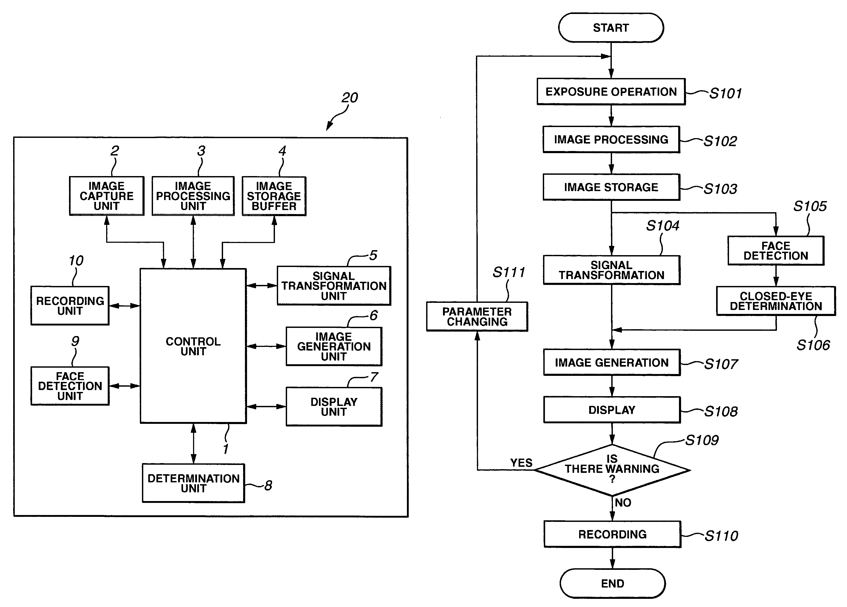
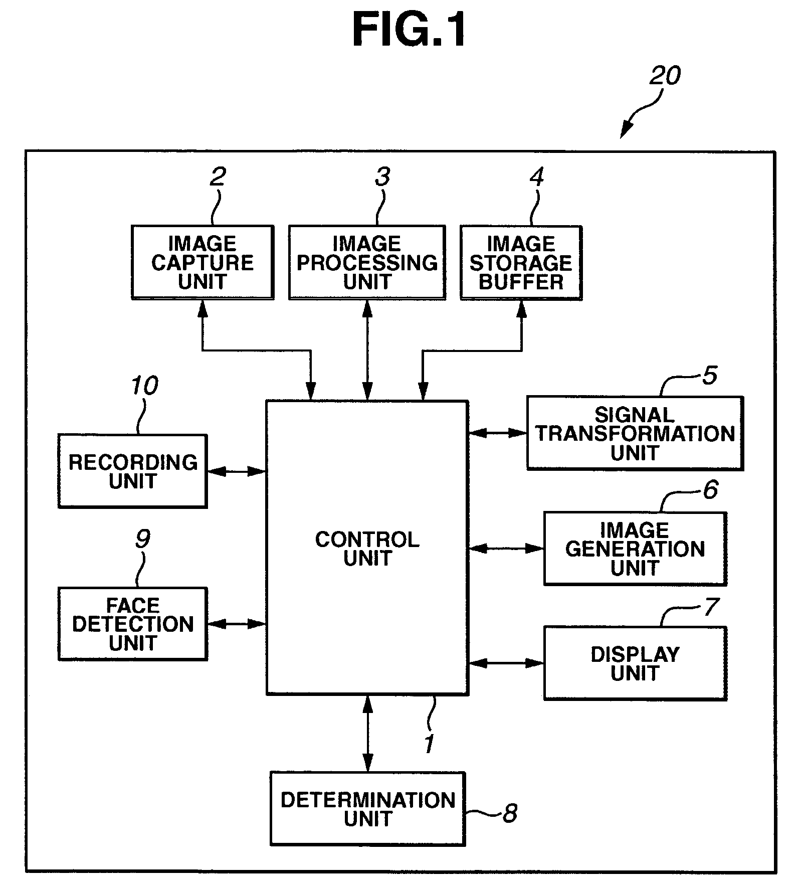
[0033]FIG. 1 shows a configuration of an image capture apparatus 20 according to a first embodiment of the present invention. Description will be made by taking an example of a digital camera as the image capture apparatus 20.

[0034]Referring to FIG. 1, a control unit 1 controls a signal for controlling each function of the image capture apparatus 20.

[0035]An image capture unit 2 includes a solid-state image sensor such as a charge-coupled device (CCD) or a complementary metal-oxide semiconductor (CMOS) having a photoelectric conversion function, an imaging optical system for guiding subject light to the solid-state image sensor, a light amount adjustment member constituted of a diaphragm or a shutter for adjusting an amount of light reaching the solid-state image sensor, an auto-gain controller (AGC) for adjusting a gain of an output signal of the solid-state image sensor, and the like.

[0036]An image processing unit 3 receives a signal output from the image capture unit 2 and genera...

second embodiment

[0104]Next, an image capture apparatus according to a second embodiment of the present invention will be described. The description will focus on differences from the first embodiment.

[0105]According to the second embodiment, an occurrence of a red-eye phenomenon in a subject is a criterion for execution of warning.

[0106]As is well known, the red-eye phenomenon is that in the case of capturing a person under a situation of low illuminance, light is emitted from a flash apparatus to execute capturing, and the flash light emitted from the flash apparatus is reflected on the back of each eyeball, causing eyes of the person to be photographed red.

[0107]The determination unit 8 in the second embodiment determines an occurrence of a red-eye phenomenon on a face detected by the face detection unit 9.

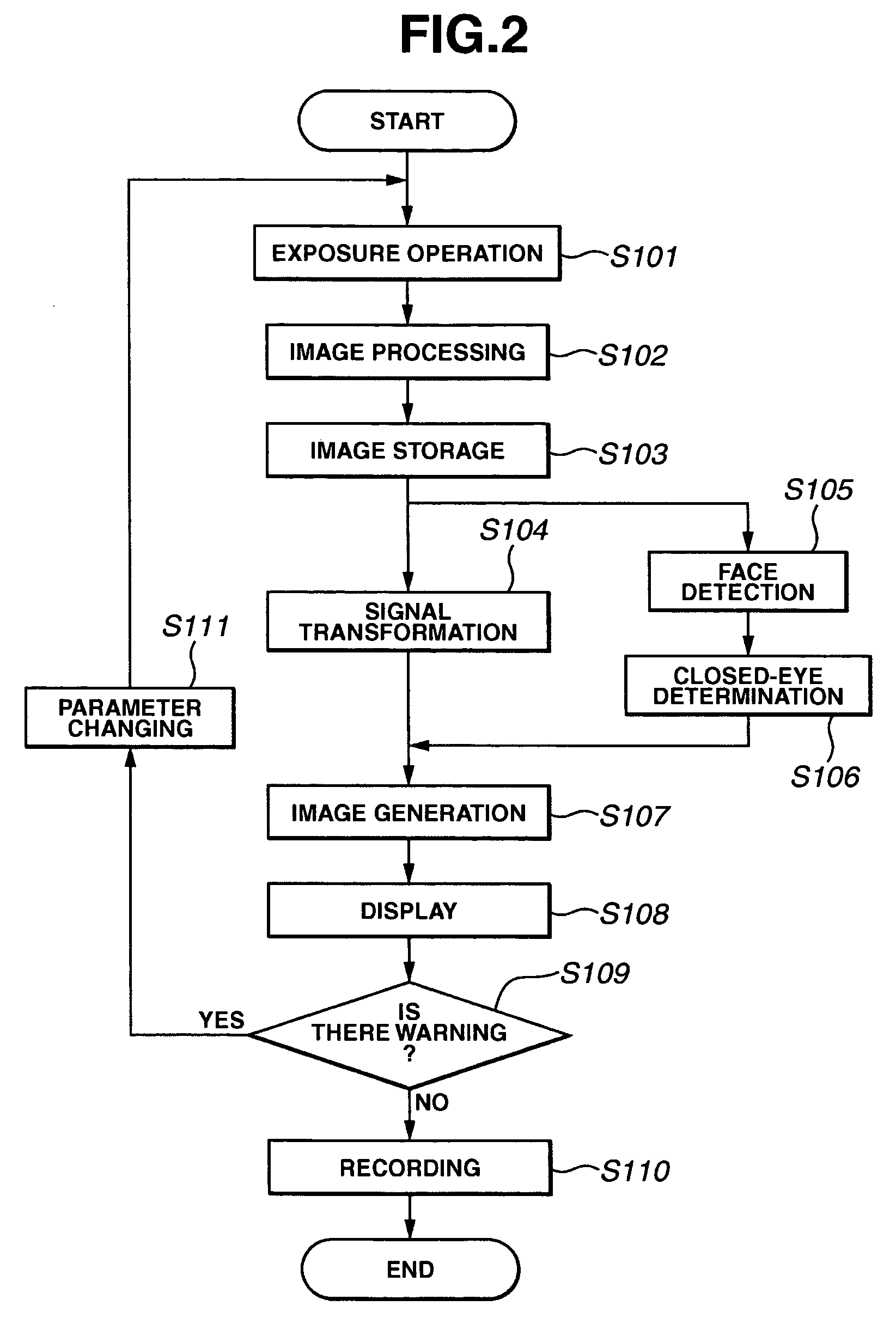
[0108]FIG. 9 is a flowchart illustrating a flow of processing according to the second embodiment.

[0109]The flow is different from that of FIG. 2 in that a red-eye phenomenon is detected from a ...

third embodiment

[0120]An image capture apparatus according to a third embodiment of the present invention will be described. According to the second embodiment, the occurrence of a red-eye phenomenon is a criterion for warning. According to the third embodiment, however, an in-focus state or a blurring state of a face area of a subject is a criterion for warning.

[0121]The determination unit 8 in the third embodiment determines a blurring state or an in-focus state of a face detected by the face detection unit 9.

[0122]Generally, as images unsuited for capturing, there are a blurred image and an out-of-focus image. Blurring is classified into a camera shake caused by a camera being moved when a shutter button is pressed and a subject shake caused by a subject moving.

[0123]In both cases, an image area frequently moves in a fixed direction. For example, as a frequency analysis method, there is a method of detecting blurring if specific frequency components that are absent in normal images are determine...


PUM


Abstract

An image capture apparatus, such as a digital camera or a digital still camera, is capable of easily capturing an optimal image by determining a state of a subject via image processing during capturing, and executing re-capturing or giving a warning to prompt re-capturing according to a result of the determination.

Description

BACKGROUND OF THE INVENTION[0001]1. Field of the Invention[0002]The present invention relates to a control method facilitating capturing an optimal image in an image capture apparatus, such as a digital camera or a digital video camera.[0003]2. Description of the Related Art[0004]As a function of checking a captured image in an image capture mode, an image capture apparatus, such as a digital camera or a digital video camera, has a REC review function of displaying a photographed image on a liquid crystal display (LCD) immediately after capturing the image.[0005]In a reproduction mode (playback mode), the image capture apparatus has a function of sequentially displaying photographed images according to a user's operation. In the image capture apparatus (the digital camera or the digital video camera), when such functions are used, since a screen size is small in an electronic viewfinder (EVF) which is used for checking captured images, the captured images are reduced to be displayed...

Claims


Application Information

Patent Timeline
Patent Type & Authority Patents(United States)
IPC IPC(8): G03B17/00G03B13/00G03B3/00G03B9/02H04N5/222H04N1/21H04N5/232
CPCH04N5/23293H04N1/2112H04N23/61H04N23/634H04N1/00867H04N23/63
Inventor FUKUI, TAKAAKI
Owner CANON KK
Why Eureka
Try Eureka