Retaining lines in bypass groove on downhole equipment

a technology of bypass grooves and downhole equipment, which is applied in the direction of drilling casings, drilling pipes, borehole/well accessories, etc., can solve the problems of damage to control lines or lines, inability to deliver tools, and increased the diameter of tools being run

Active Publication Date: 2008-10-07
BAKER HUGHES INC
View PDF15 Cites 29 Cited by
  • Summary
  • Abstract
  • Description
  • Claims
  • Application Information

AI Technical Summary

Problems solved by technology

Frequently, a running string or production string is run through tight clearances and that causes a concern about damage to the control line or lines that are frequently run along side.
Those skilled in the art will appreciate that a big problem in this design was that it added to the diameter of the tool that was being run in.
In some cases that would make it impossible to deliver the tool because the drift diameters downhole were simply not large enough.
There were no provisions for retaining the control line in the groove except external bands that simply defeated the purpose of the recessed groove by adding back bulk that would either prevent advancement of the assembly altogether or it would present components sticking out that could get snagged and stick the tool or get sheared off.

Method used


Image

  • Retaining lines in bypass groove on downhole equipment
  • Retaining lines in bypass groove on downhole equipment
  • Retaining lines in bypass groove on downhole equipment

Examples


Embodiment Construction

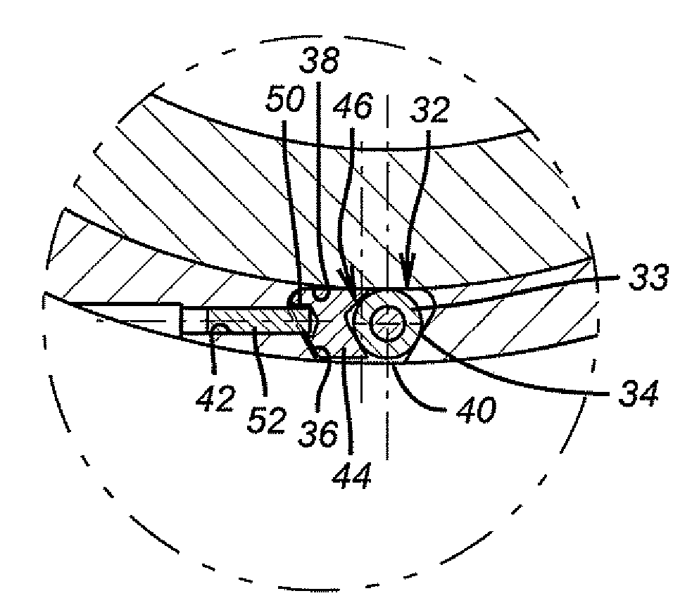
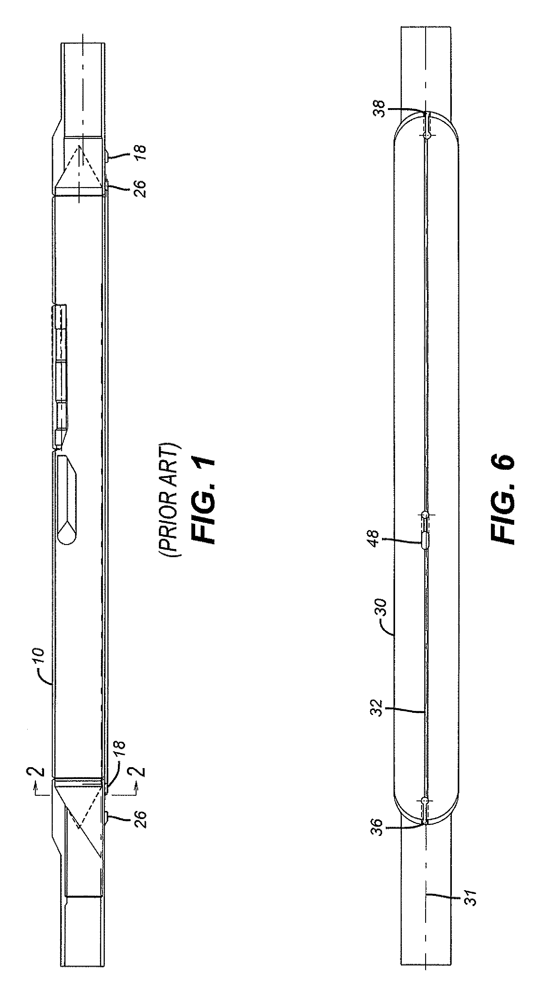
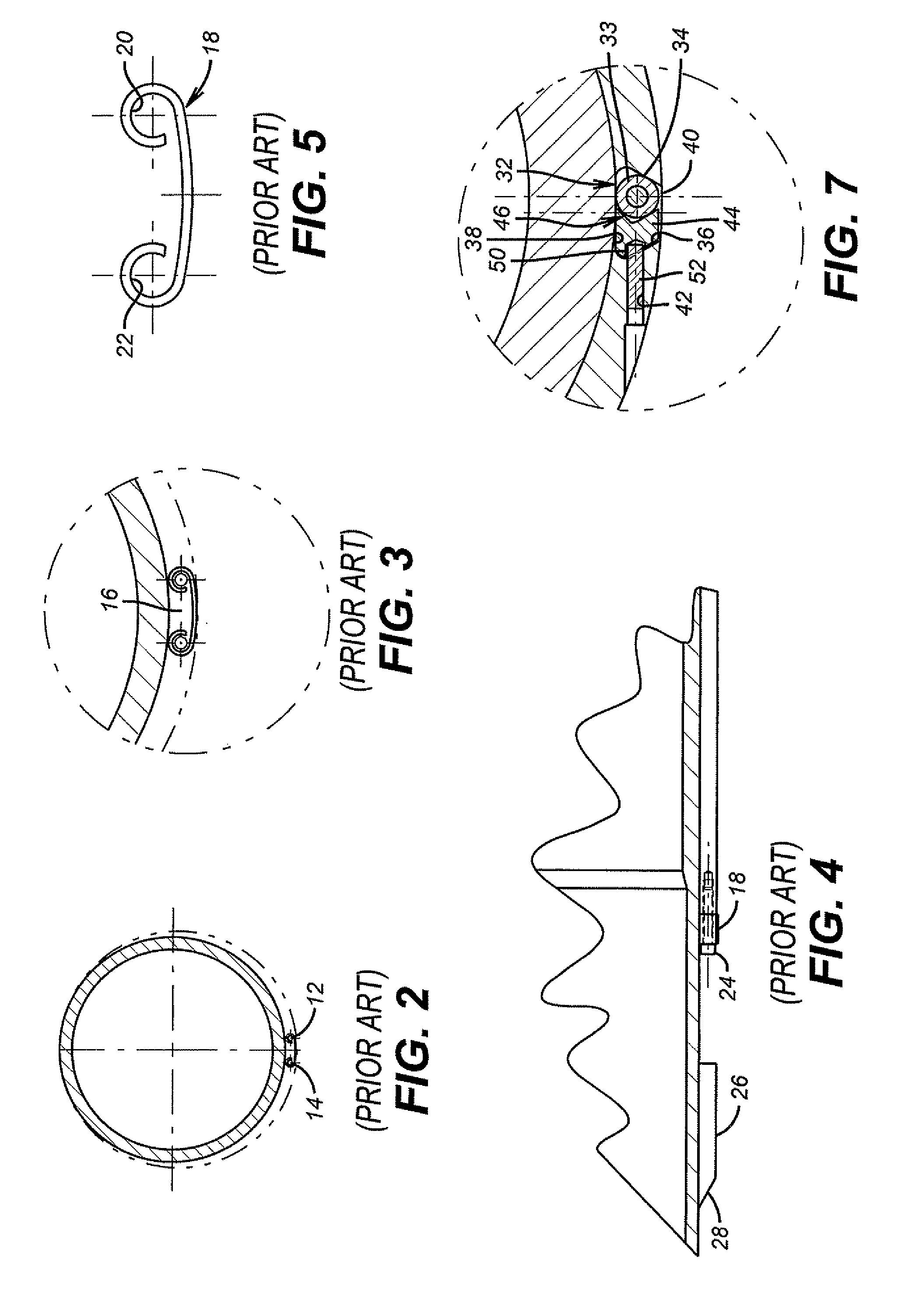
[0015]FIG. 6 shows a downhole tool such as a side pocket mandrel 30. Preferably it has a longitudinal slot 32 aligned with its central axis 31. Preferably, slot 32 is open on opposed ends 36 and 38. In selected sections, as shown in FIG. 7, slot 32 has opposing reverse sloped walls 34 and 36 and an inside wall 38. In other portions the slot 32 can have a u-shape or another cross-section. It can be dovetailed as shown in FIG. 7 for its entire length, as another option. A “control line”33 specially defined herein to mean any type of an extending member used downhole to convey flow, pressure, power, signals or for any other downhole purpose, is inserted through the opening 40 and moved to a corner formed by inside wall 38 and one of the adjacent sloped walls, in this case 34 since bore 42 comes through wall 36. A wedge 44 has a leading bevel surface 46 to engage control line 33 to push it into the corner defined by surfaces 34 and 38. Except at ends 36 and 38 where the wedge 44 can sim...


PUM


Abstract

One or more control lines or other types of lines can be run past a downhole tool such as a side pocket mandrel, for example, in a longitudinal groove with a retaining feature for the control line where the assembly leaves little to stick out and get damaged on run in or on pulling out of the hole. In the preferred version, the groove is a dovetail and at least one retainer can be slipped into the dovetail. Lateral bores into the dovetail allow pins to be driven into a wedge shaped retainer to force it against the control line or lines such that the shape of the dovetail and the shape of the wedge retainer trap the control line within the dovetail. Upon assembly, nothing sticks out from the dovetail or the downhole tool.

Description

FIELD OF THE INVENTION[0001]The field of this invention is downhole tools that have control lines or other types of lines that run past them and ways of retaining and protecting said line or lines as they pass the downhole tool.BACKGROUND OF THE INVENTION[0002]A frequent occurrence in downhole operations is the need to run control lines along a string and past downhole equipment to reach yet other equipment. The lines can conduct hydraulic fluid under pressure, or electric power, or electric signals in either direction. Frequently, a running string or production string is run through tight clearances and that causes a concern about damage to the control line or lines that are frequently run along side.[0003]One solution that has been tried in the past is illustrated in FIGS. 1-5. FIG. 1 shows a side pocket mandrel 10, as an example. FIG. 2 is a section along lines 2-2 of FIG. 1 and shows the use of two parallel rods 12 and 14 that are shown in bigger scale in FIG. 3. In between rods...

Claims


Application Information

Patent Timeline
Patent Type & Authority Patents(United States)
IPC IPC(8): E21B17/10
CPCE21B17/1035
Inventor HOLT, JAMES H.BEAM, CLARK W.
Owner BAKER HUGHES INC
Why Eureka
Try Eureka