Magnetic mounting platform

a technology of magnetic mounting platform and mounting plate, which is applied in the direction of machine supports, other domestic objects, mechanical apparatus, etc., can solve the problems of limiting the usefulness of known magnetic mounting platform, and achieve the effect of high friction coefficien

Inactive Publication Date: 2008-10-07
CARNEVALI JEFFREY D
View PDF19 Cites 124 Cited by
  • Summary
  • Abstract
  • Description
  • Claims
  • Application Information

AI Technical Summary

Problems solved by technology

These and other known magnetic mounting platforms each suffer limitations that limit their usefulness as mounting platforms for handheld devices in modern automobiles and other modern vehicles.

Method used


Image

  • Magnetic mounting platform
  • Magnetic mounting platform
  • Magnetic mounting platform

Examples


Embodiment Construction

[0017]In the Figures, like numerals indicate like elements.

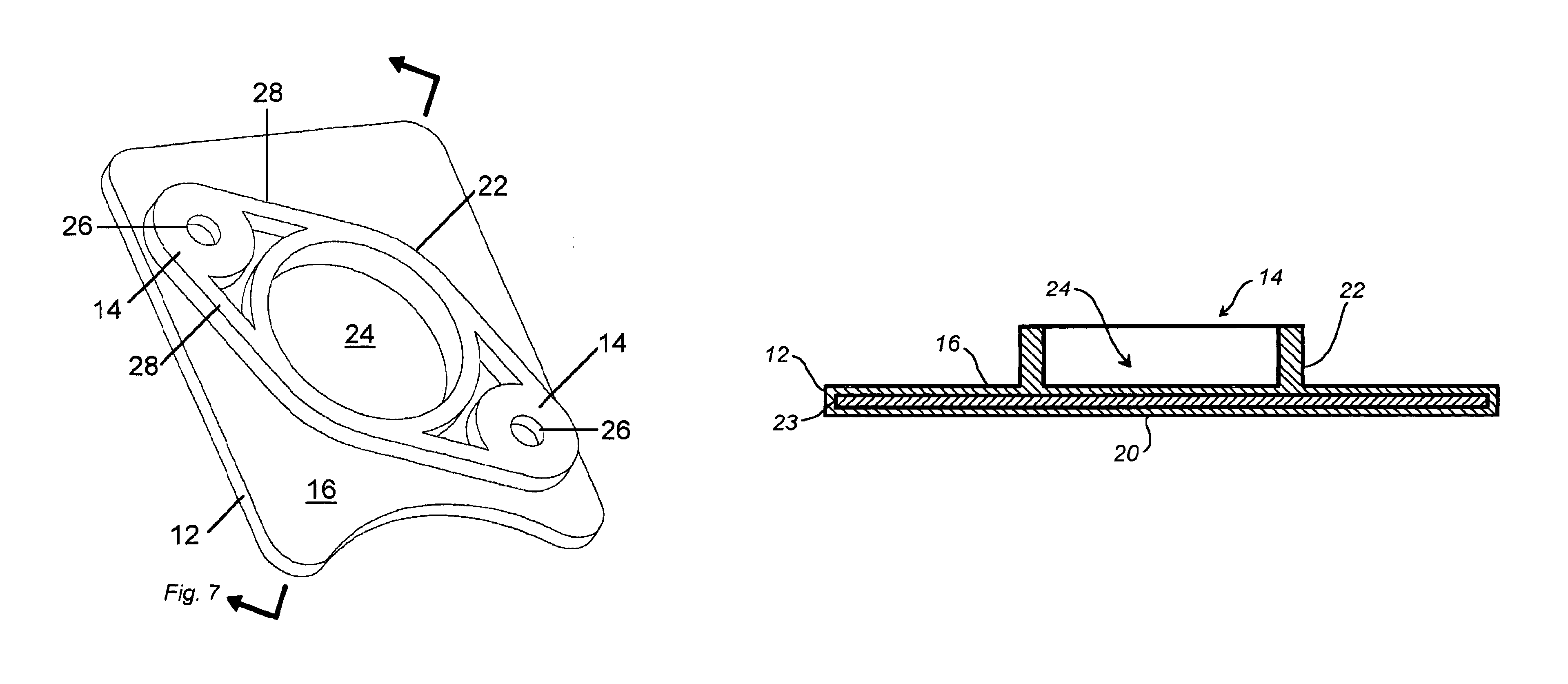
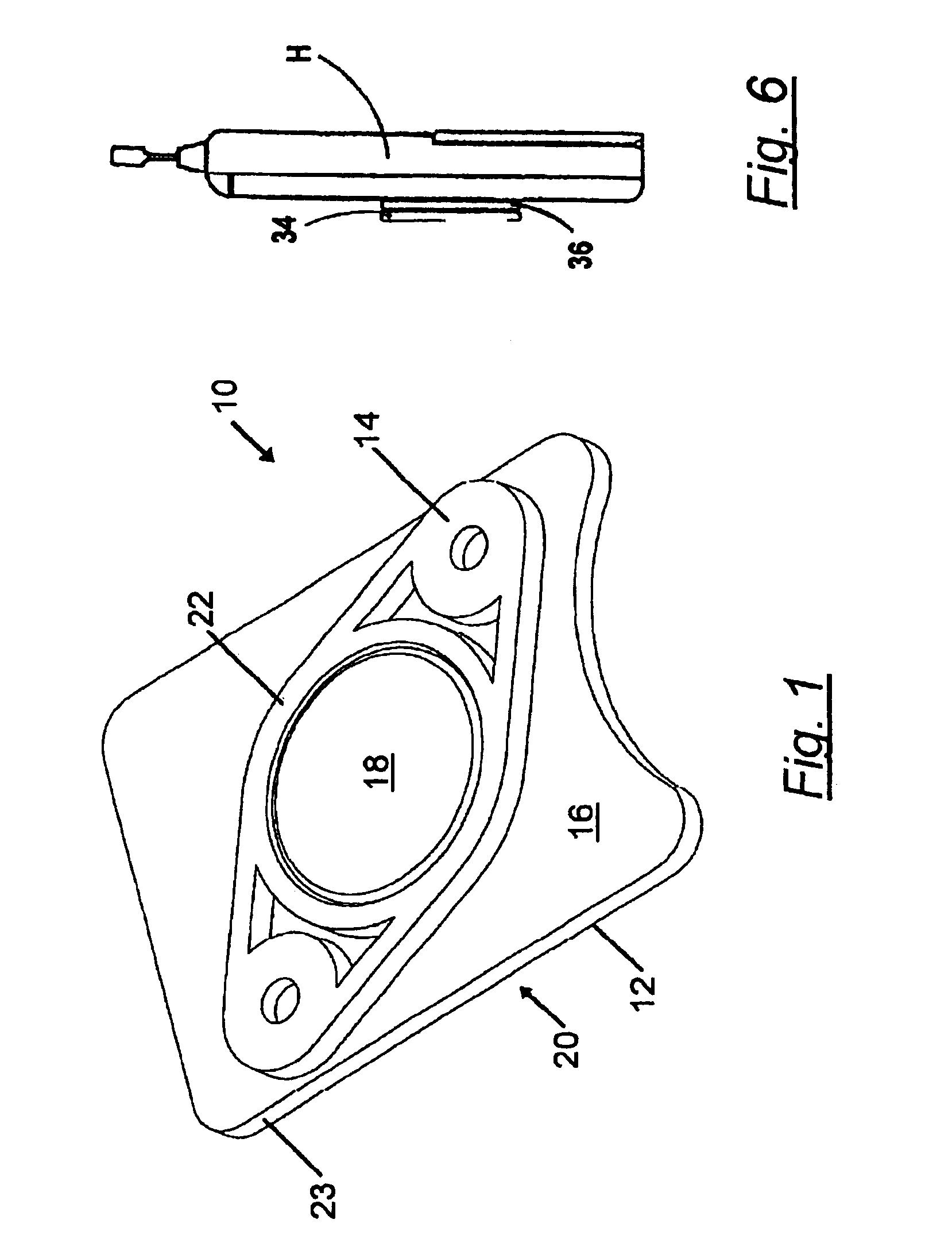
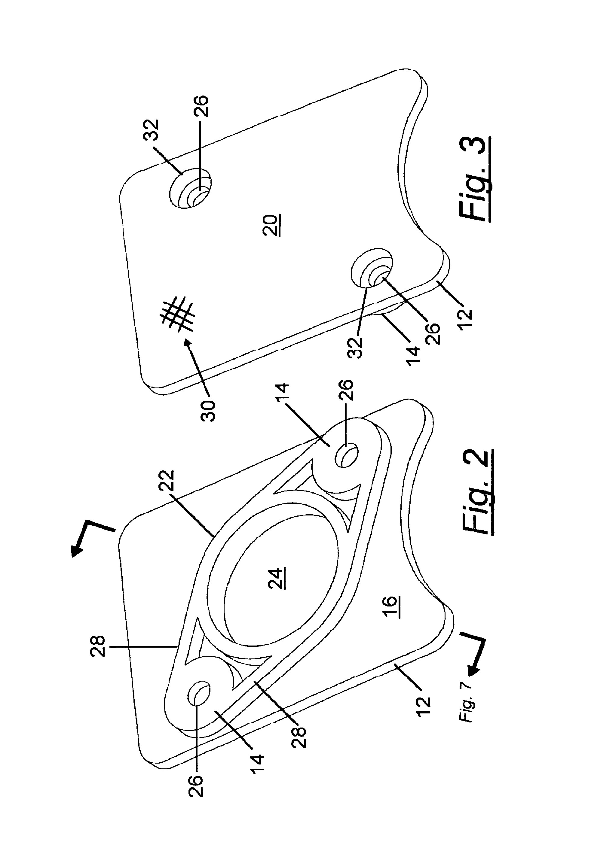
[0018]The present invention is an apparatus for removably retaining handheld devices by means of magnetic attraction. The magnetic mounting platform of the invention provides a substantially flat support surface backed by an interface structure that operates as means for securing the magnetic mounting platform assembly to an external mounting surface. A permanent magnet is disposed within a cavity that positions magnet in close proximity to the flat support surface. According to one embodiment of the invention, the interface structure also operates as means for capturing and securing the magnet between the pad and the mounting surface.

[0019]According to one embodiment of the invention, the flat support surface is embodied as a thin support pad of pliant elastomeric material that is sufficiently flexible to conform to device surfaces having a non-planar contour as is common with modern handheld electronic devices such as cell...


PUM


Abstract

A magnetic mounting platform assembly for removably retaining handheld devices using magnetic attraction. The magnetic mounting platform assembly provides a substantially flat support surface backed by an interface structure that secures the magnetic mounting platform assembly to an external mounting surface. A permanent magnet is disposed within a cavity that positions magnet in close proximity to the flat support surface. According to one embodiment of the invention, the interface structure also captures and secures the magnet between the pad and the mounting surface.

Description

FIELD OF THE INVENTION[0001]The present invention relates to the field of device mounting platforms, and in particular to handheld device mounting platforms operable by means of magnetic attraction.BACKGROUND OF THE INVENTION[0002]Mounting platforms for handheld devices and other small articles operable by means of magnetic attraction are generally well-known. Several of these magnetic mounting platforms are known for supporting handheld cell phones on the dashboard of an automobile. One example is shown in U.S. Pat. No. 5,992,807 entitled, UNIVERSAL MAGNETIC STAND FOR CELL PHONES, issued to Tarulli on Nov. 30, 1999, which is incorporated herein by reference, which describes a magnet that is permanently secured to the dashboard. Attraction between the magnet and metal parts normally found in the cell phone cause the cell phone to be removably retained on the dashboard so that it may be lifted off manually and manually replaced on the magnet. A rubber layer is provided on the magnet'...

Claims


Application Information

Patent Timeline
Patent Type & Authority Patents(United States)
IPC IPC(8): A47G1/17F16M11/04F16M11/14
CPCF16M11/04F16M13/00F16M2200/022
Inventor CARNEVALI, JEFFREY D.
Owner CARNEVALI JEFFREY D
Why Eureka
Try Eureka