
Monitoring and security system and method

a security system and monitoring system technology, applied in frequency-division multiplex, instruments, applications, etc., can solve the problems of limited to the vehicle and its location, inability to communicate with the user's vehicle, and certainly not providing other vehicle diagnostic monitoring and reporting functions, so as to enhance customer loyalty

Inactive Publication Date: 2006-06-15
SMITH TIMOTHY D +1
View PDF11 Cites 124 Cited by
  • Summary
  • Abstract
  • Description
  • Claims
  • Application Information

AI Technical Summary

Benefits of technology

[0022] This system and method benefits the vehicle manufacturer and service provider by enhancing customer loyalty and providing timely emergency response and feedback to solve engineering and manufacturing problems. The system and method benefits the users by providing a small personal device that comfortably fits into their pocket that integrates their wants and needs, within and away from their vehicle.

Problems solved by technology

The emergency and location based services, although extremely useful to an individual person regardless of their proximity to their vehicle, are limited to the vehicle and its location, and are unavailable when the user is outside or away from the automobile.
There are devices that fulfill the emergency and location based services, such as products and services from “Life Alert” and “Wherify,” but these products are unable to communicate with the user's vehicle and notify the service of an in-vehicle emergency event such as a crash or an airbag deployment and they certainly do not provide other vehicle diagnostic monitoring and reporting functions.
However, these devices may not operate effectively in circumstances where the user is incapacitated.
In general, however, a user doesn't want to carry or pay for multiple devices or services.
Automotive OEM's want product offerings to compete with GM but do not want to take on the burden and expense of building an “OnStar” type infrastructure and do not want to license a GM branded product.

Method used


Image

  • Monitoring and security system and method
  • Monitoring and security system and method
  • Monitoring and security system and method

Examples


Embodiment Construction

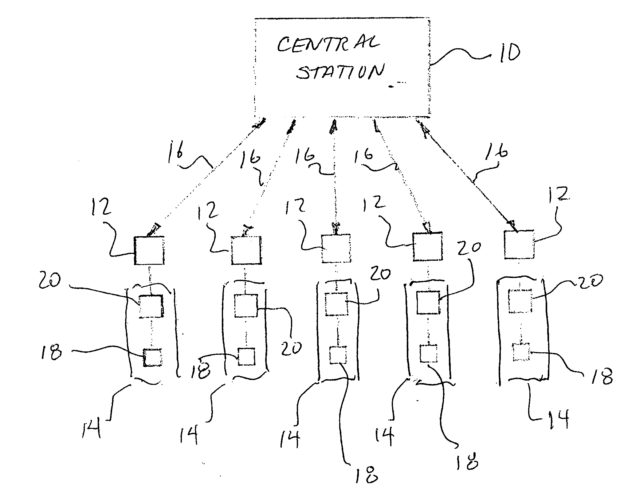
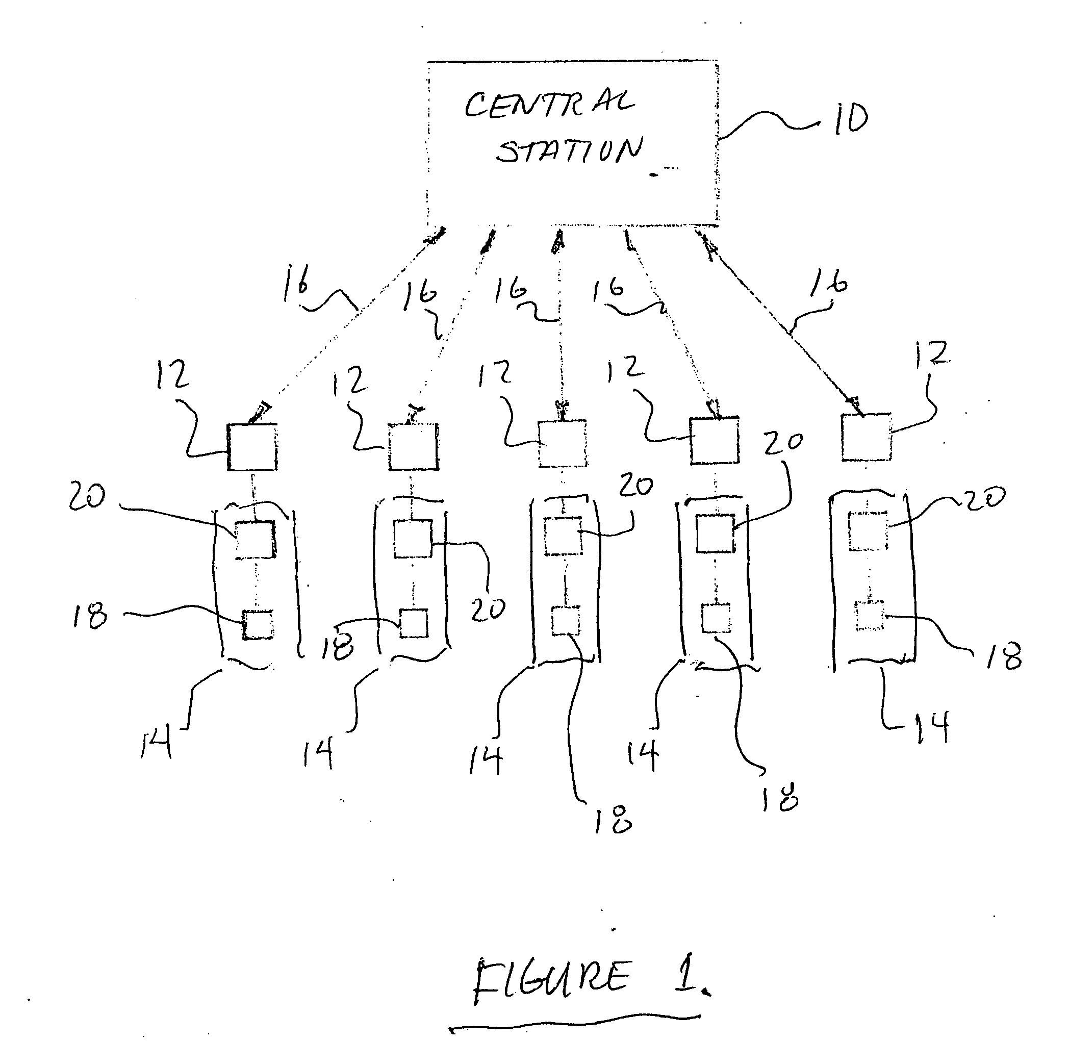
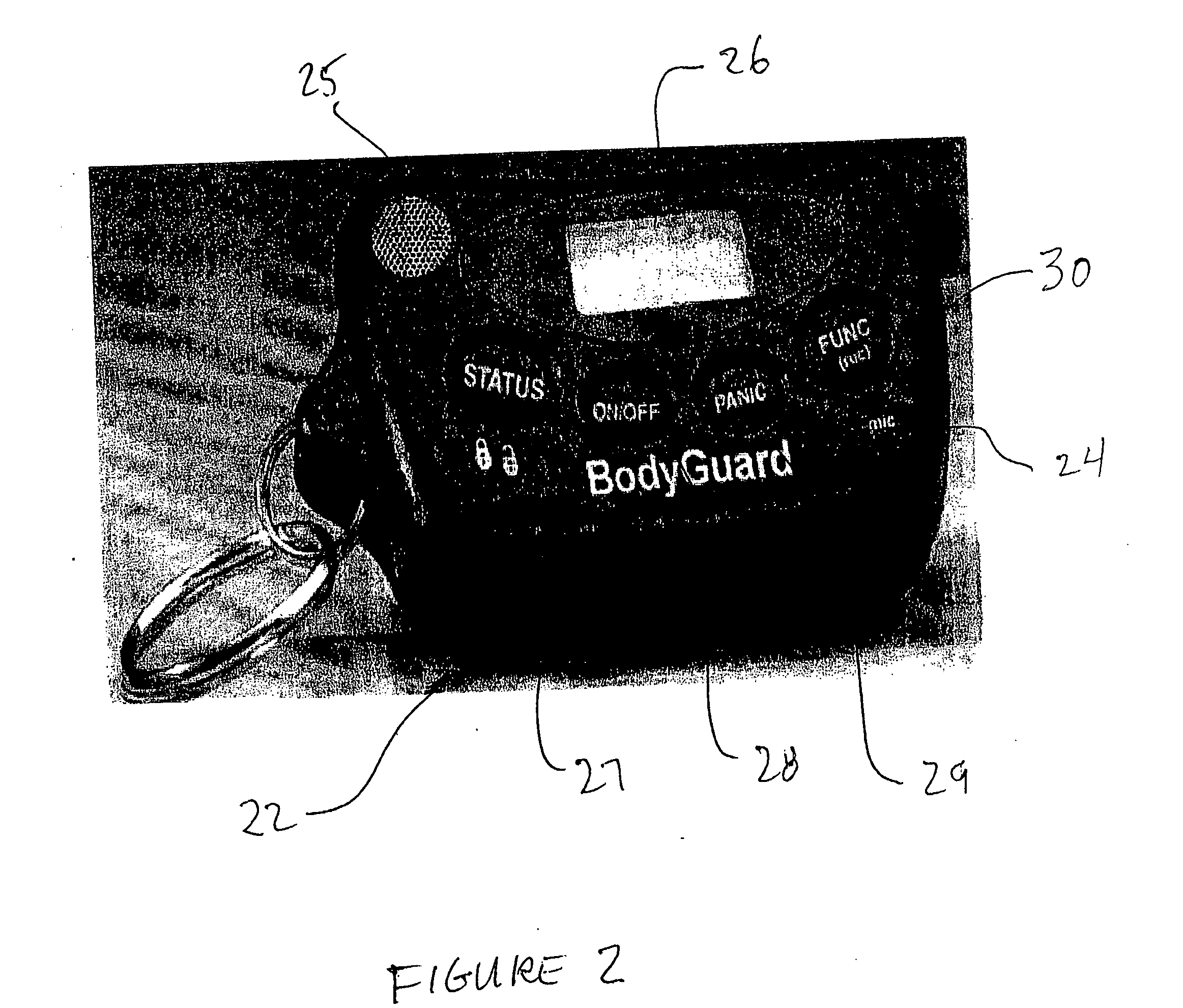
[0027] Referring now to the drawings, and more particularly to FIGS. 1-2, there are shown preferred embodiments of the method and structures according to the present invention. As illustrated in FIG. 1, one preferred embodiment of the invention comprises a central station 10, a plurality of portable remote user stations 12, and a plurality of suitably equipped vehicles 14.

[0028] The central station 10 includes a call center to receive audio communications and data transmitted from each of the remote stations 12. The central station also includes data processing capabilities for analyzing various data received from the remote stations 12. All of the audio and data transmissions between the central and remote stations is effected over convention wireless communications networks, illustrated schematically as lines 16. The central station 10 can also locate each of the remote user stations 12 via GPS.

[0029] The remote stations 12 may take many forms. These devices are most preferably ...


PUM


Abstract

A system and method simplifying, combining and improving vehicle and personal diagnostic monitoring and reporting, automatic vehicle emergency event notification, personal emergency distress notification, vehicle and personal location notification, vehicle and personal threat notification and remote vehicle operation (door locks, lights, horn and other systems). System and method include a device within the vehicle, or carried by an individual, and having a wireless communication capability, providing two way communication of data via a hand-held device or key fob, and a remote call center capable of storing, analyzing and assessing services required and communicating back the results of that assessment. Services would include roadside mechanic assistance, towing, informed Public Safety Answering Point (PSAP) notification (including assessment of severity of emergency) and threat notification.

Description

RELATED APPLICATIONS [0001] This is a continuation-in-part of U.S. patent application Ser. No. 10 / 944,675 filed Sep. 17, 2004.BACKGROUND OF THE INVENTION [0002] 1. Field of the Invention [0003] The present invention generally relates to personal monitoring equipment capable of automatic emergency event notification, personal emergency distress notification, vehicle and personal location notification, and personal threat notification. [0004] 2. Description of the Related Art [0005] Motor vehicles contain complex mechanical systems that are monitored and regulated by on-board computer systems often known as electronic vehicle control units (VCUs). [0006] Such VCUs monitor various vehicle systems including powertrain performance, crash sensors, air bag deployment and the like, and store codes associated with behaviors that can subsequently be used to diagnose vehicular systems issues. [0007] These codes are generally used to trigger a message on the vehicle console, for example: “check...

Claims


Application Information

Patent Timeline
Patent Type & Authority Applications(United States)
IPC IPC(8): G08B29/00A61B5/00G08B19/00G08B1/00G08B1/08G08B23/00
CPCG07C5/008G07C2209/63
Inventor SMITH, TIMOTHY D.BINGHAM, ANTHONY
Owner SMITH TIMOTHY D
Learn More