Drip chamber dropper bottle

a dropper bottle and dropper technology, applied in the field of dropper bottles, can solve the problems of inability to withdraw the last amount of medicine from the dropper bottle, waste of the last dosage or dosage of medicine, and gap between the distal end of the tapered cylinder and the bottom of the dropper bottl

Inactive Publication Date: 2008-10-14
RUTGERS THE STATE UNIV
View PDF19 Cites 7 Cited by
  • Summary
  • Abstract
  • Description
  • Claims
  • Application Information

AI Technical Summary

Problems solved by technology

However, there is typically a gap between the distal end of the tapered cylinder and the bottom of the dropper bottle.
This results in the inability to withdraw the last amount of medicine from the dropper bottle, i.e., the medicine remaining in the bottle but below the distal end of the dropper apparatus.
This leads to the waste of the last dosage or dosages of medicine.
Another problem associated with dropper bottles of the prior art is the inability to effectively judge whether a full dose, or a portion of a dose remains in the bottle.

Method used


Image

  • Drip chamber dropper bottle
  • Drip chamber dropper bottle

Examples


Embodiment Construction

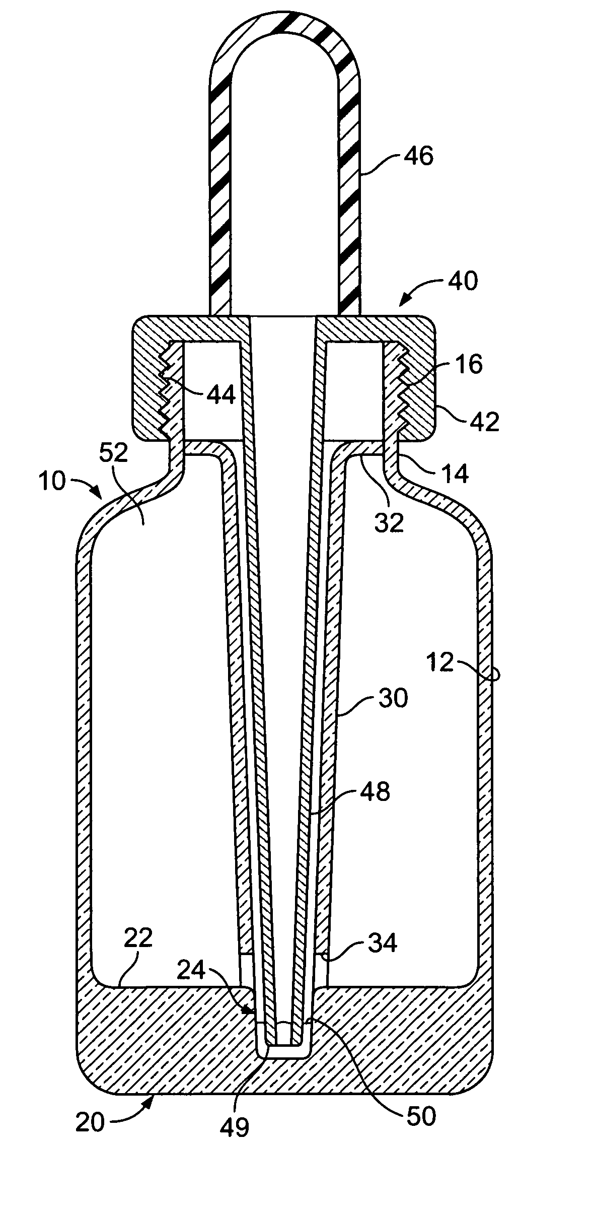
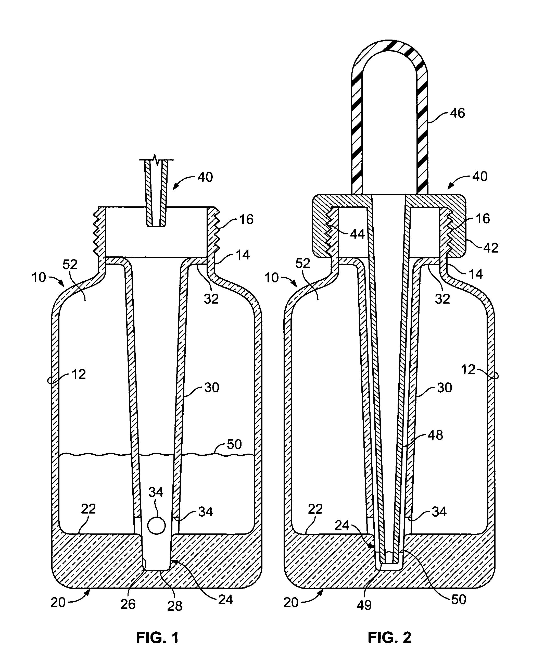
[0011]The present invention relates to a drip chamber dropper bottle 10 including a bottle portion having a central recess 24 in a bottom wall 22 of the bottle 10, and a central tapered cylindrical dropper chamber 30 extending from an upper end of the bottle 10 to the central recess 24.

[0012]Referring to FIG. 1, the drip chamber dropper bottle 10 of the present invention is shown cross-section. The bottle 10 can be sized and shaped in any desired configuration, and can be made of any desired material. As shown in FIG. 1, the bottle 10 includes an outer wall 12 defining the shape and size of the bottle 10. At an upper area of the bottle 10, the outer wall 12 is necked to throat area 14 which bears external threads 16 for engaging a dropper 40 as will be hereinafter discussed.

[0013]The lower portion of the bottle 10 comprises a base 20 which joins with the outer wall 12 along the circumference of the base 20. The base 20 has an exterior surface and an interior surface defined by the i...


PUM

PropertyMeasurementUnit
areaaaaaaaaaaa
thicknessaaaaaaaaaa
diameteraaaaaaaaaa

Abstract

A chamber dropper bottle is disclosed that is sized to contain medicine. The dropper bottle includes a central recess in a bottom wall of the bottle. The recess is sized to accommodate a single dose of medicine. A central tapered cylindrical dropper chamber extends into the recess, while an annular medicine chamber is positioned about the central tapered cylindrical dropper chamber. The central tapered cylindrical dropper chamber includes one or more apertures sized to allow fluid to flow between the annular medicine chamber, the central tapered cylindrical dropper chamber and the recess.

Description

BACKGROUND OF THE INVENTION[0001]1. Field of the Invention[0002]The present invention relates to a dropper bottle for dispensing doses of liquid medicine.[0003]2. Related Art[0004]Dropper bottles are known in the art for dispensing medicine. Dropper bottles generally include a bottle for holding a substance such as a liquid medicine, and a dropper apparatus that is used in connection with the bottle. The dropper apparatus typically includes a squeezable bulb attached to a cap that threadably engages with the bottle, and a tapered cylinder that extends into the bottle. In operation, the squeezable bulb is squeezed to force air out of the tapered cylinder. The squeezable bulb is then released, sucking liquid medicine into the tapered cylinder. The dropper apparatus is then withdrawn from the bottle, placed at a location where liquid medicine is to be discharged, and the squeezable bulb is again squeezed, this time forcing the liquid medicine from the tapered cylinder.[0005]The tapered...

Claims


Application Information

Patent Timeline
Patent Type & Authority Patents(United States)
IPC IPC(8): B65B1/04B65D37/00
CPCB65D47/18A61J1/00B01L3/0272B65D2231/008
Inventor BARONE, JOSEPH
Owner RUTGERS THE STATE UNIV
Why Eureka
Try Eureka