Handpiece for dental or surgical use with locking mechanism

a technology of locking mechanism and handpiece, which is applied in the field of handpiece for dental or surgical use, can solve the problems of large mass of relativly strong collet spring, inability to generally be centred with precision, and large drawback of a part that rotates very fast, so as to facilitate the manoeuvring of the collet, prevent inadvertent manipulation, and simplify the arrangement of the roller bearings

Inactive Publication Date: 2008-11-11
BIEN AIR HLDG SA
View PDF7 Cites 14 Cited by
  • Summary
  • Abstract
  • Description
  • Claims
  • Application Information

AI Technical Summary

Benefits of technology

[0008]It is an object of the present invention to prevent the aforementioned drawbacks of the prior art, owing to an arrangement with strong gripping at the collet jaws, while limiting the axial forces occurring in the gripping and releasing mechanism. In particular, the gripping and releasing mechanisms should be arranged so as to facilitate manoeuvring of the collet and prevent inadvertent manipulations. It is an additional object of the invention to simplify the arrangement of the roller bearings of the main bearings of the handpiece, in particular by reducing the axial loads on at least one of them.
[0010]With this combination of features, quite strong gripping can be obtained for the collet without large axial forces appearing in the rotating part of the handpiece, and the gripping and releasing devices can also be lightened owing to this reduction in stress. According to a preferred embodiment, the helical slot of the releasing mechanism can thus include, laterally, close to the end thereof where the ball is situated when the releasing mechanism is in the inactive position, a flexible tongue which holds by snap fitting ball into this position, in order to prevent inadvertent releasing.
[0011]The sliding sleeve can be drawn in the gripping direction by a relatively small spring. In a particularly advantageous variant, a hollow can be arranged in the cam surface, forming a catch that holds the sliding sleeve in place via the resilience of the collet arms, which allows the usual clamping spring to be omitted. Consequently, the releasing manoeuvre no longer has to overcome the axial thrust caused by the spring.
[0012]According to a second aspect, the invention concerns a handpiece of the type indicated in the preamble hereinbefore, characterized in that the gripping mechanism includes a sliding sleeve mounted on the hollow shaft and, for each arm of the collet, a transmission element arranged in a radial hole of the hollow shaft between said arm support surface and an inner cam surface of the sliding sleeve, and in that the gripping mechanism includes a sliding collar arranged in the fixed tubular shaft and activated by a manual control member such that the latter can move the sliding collar axially to drive the sliding sleeve of the gripping mechanism so as to release the collet, in that said cam surface includes a first hollow, provided with an axially inclined surface, and a second hollow, shallower than the first and separated therefrom by a projecting portion, and in that the arms of the collet are resilient, such that the second hollows form a catch that holds the sliding sleeve in place when said transmission elements are engaged in the second hollows by the resilience of the collet arms. This also provides the advantages mentioned in the preceding paragraph.
[0013]According to a preferred embodiment, each arm of the collet is formed by a lever, a first end of which is attached to the annular part by a hinge and whose said support surface is axially at a distance from said hinge, the jaw being located closer to the hinge than to the support surface. Consequently said centripetal forces that have to be exerted by the gripping mechanism can be reduced, since they are multiplied by the collet levers to exert a strong gripping force on the tool.

Problems solved by technology

Moreover, a relatively strong collet spring has a relatively large mass, which constitutes a considerable drawback for a part that rotates very fast and which cannot generally be centred with precision.
The resulting vibrations increase with the mass of the spring.
A big drawback of this system is that it imposes a strong axial load on the bearings while the collet is being clamped, and thus during work.
Moreover, the front bearing support system is not rigid enough to prevent the tool vibrating as soon as speed is high.

Method used


Image

  • Handpiece for dental or surgical use with locking mechanism
  • Handpiece for dental or surgical use with locking mechanism
  • Handpiece for dental or surgical use with locking mechanism

Examples


Embodiment Construction

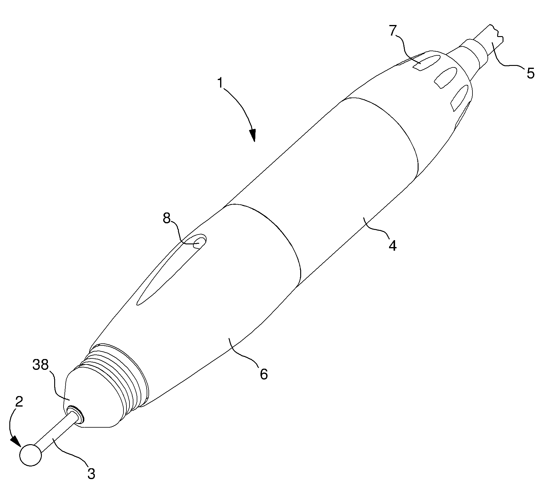
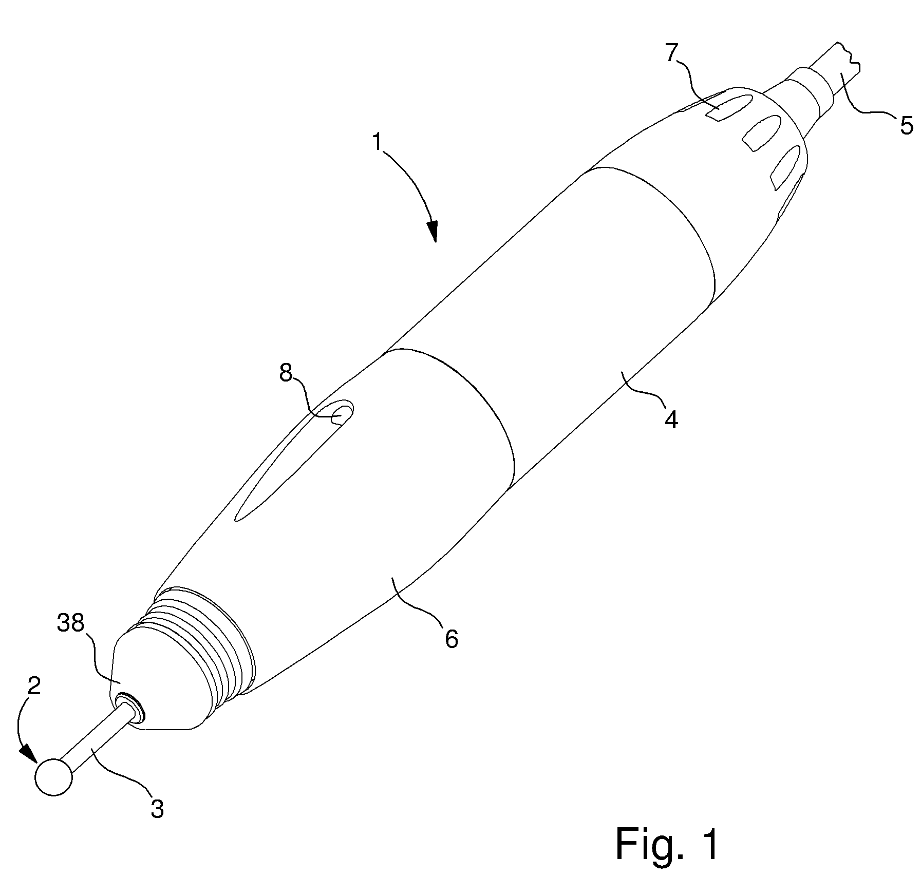
[0022]FIG. 1 shows a handpiece 1 for dental or surgical use, wherein the various embodiments of the invention, which will be described hereinafter, can be found. The handpiece is fitted with a removable rotating tool 2 having a cylindrical shank 3 which is clamped or gripped into a rotating collet of handpiece 1. The latter contains a motor, in this case an electric motor, for rotating tool 2 at high speed. The motor is housed in the main body 4 of the handpiece and it is powered and controlled from an external unit via an electric cable 5 connected to the back of the handpiece. The operator controls the gripping and releasing of the collet by rotating a sleeve 6, rotatably mounted on body 4, in one direction or the other. References 7 and 8 design ventilation vents. This type of instrument finds application particularly in dental surgeries, in dental laboratories and in micro-surgical techniques. In the examples shown here, it is an instrument for a dental laboratory, using tools w...


PUM


Abstract

The handpiece includes at the front a collet arranged for strongly gripping the shank of a removable tool housed in guide bores. The collet includes two or several arms attached to an annular part of the collet to grip the tool shank. Preferably, the collet arms are levers each having a support surface which is far from the jaw and on which a gripping mechanism exerts a force which is multiplied by the lever. The gripping mechanism includes a sliding sleeve having an inner conical surface which produces the force on the collet levers via balls. This arrangement enables a smaller gripping spring to be used, or such spring to be omitted. The balls of the releasing mechanism are guided in helical slots having a flexible lateral strip which holds the gripping mechanism in position via a snap fit.

Description

[0001]This application claims priority on PCT / EP2005 / 001612 of Feb. 17, 2005, which claims priority from European Patent Application No. 04003520.6, filed Feb. 17, 2004.BACKGROUND OF THE INVENTION[0002]The present invention concerns a handpiece for dental or surgical use, of the type comprising: a hollow shaft rotating about a longitudinal axis and mounted via roller bearings in a fixed tubular shaft; a collet mounted in a front end of the hollow shaft and having a central channel for receiving the shank of a removable tool, the collet including axial arms distributed around the axis and each provided with a clamping or gripping jaw in the central channel; a gripping mechanism carried by the hollow shaft and arranged to exert a centripetal force on a support surface for each arm of the collet to grip the shank of the tool between the jaws of the collet; and a releasing mechanism carried at least in part by the fixed shaft and arranged to act on the gripping mechanism at least so as ...

Claims


Application Information

Patent Timeline
Patent Type & Authority Patents(United States)
IPC IPC(8): A61C1/10A61B17/16A61C1/14B23B31/20
CPCA61C1/144A61C1/147
Inventor MA TRE, LUC
Owner BIEN AIR HLDG SA
Why Eureka
Try Eureka