Wire containment cap

a technology of containment cap and wire, which is applied in the direction of coupling device connection, coupling device details, contact members penetrating/cutting insulation/cable strands, etc., can solve the problems of increasing the crosstalk due to capacitive and inductive coupling between closely spaced parallel conductors within the jack and/or plug, affecting the and the effect of termination on the crosstalk performance of the jack

Active Publication Date: 2008-11-18
PANDUIT
View PDF13 Cites 29 Cited by
  • Summary
  • Abstract
  • Description
  • Claims
  • Application Information

AI Technical Summary

Problems solved by technology

In the communications industry, as data transmission rates have steadily increased, crosstalk due to capacitive and inductive couplings among the closely spaced parallel conductors within the jack and / or plug has become increasingly problematic.
However, the wire pairs terminated to the insulation displacement contact (“IDC”) terminals at the rear portion of a jack may also affect the performance of the jack.
One problem that exists when terminating wire pairs to the IDC terminals of a jack is the effect that termination has on the crosstalk performance of a jack.
Both of these conditions may result in unintended coupling in the termination area which can degrade the crosstalk performance of the jack.
A second problem that exists when terminating wire pairs to the IDC terminals of a jack is variability.
A final issue that arises when terminating wire pairs to the IDC terminals of a jack is the difficulty of the termination process.
Typical jacks provide little assistance to the technician, resulting in occasional misterminations (e.g. a wire being terminated at an incorrect location in the jack).
Even if detailed instructions are provided with the jack, technicians may not read these instructions prior to installing the jacks.
Furthermore, a jack with a difficult termination process can increase the installation time for the technician and result in a costly installation for the customer.

Method used


Image

  • Wire containment cap
  • Wire containment cap
  • Wire containment cap

Examples


Embodiment Construction

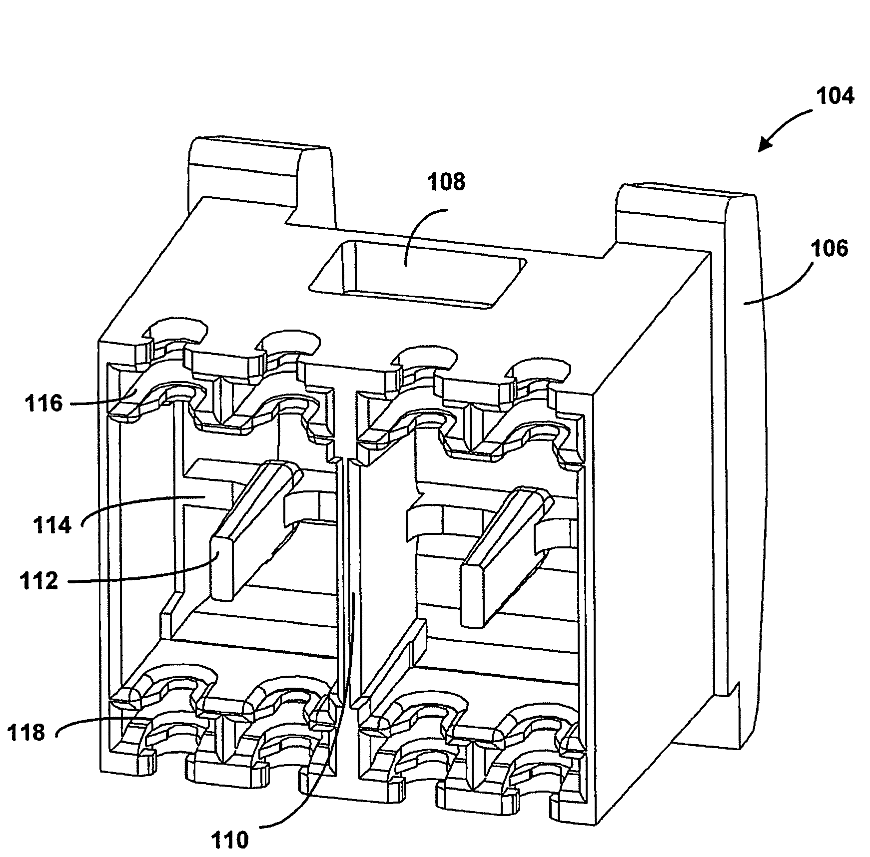
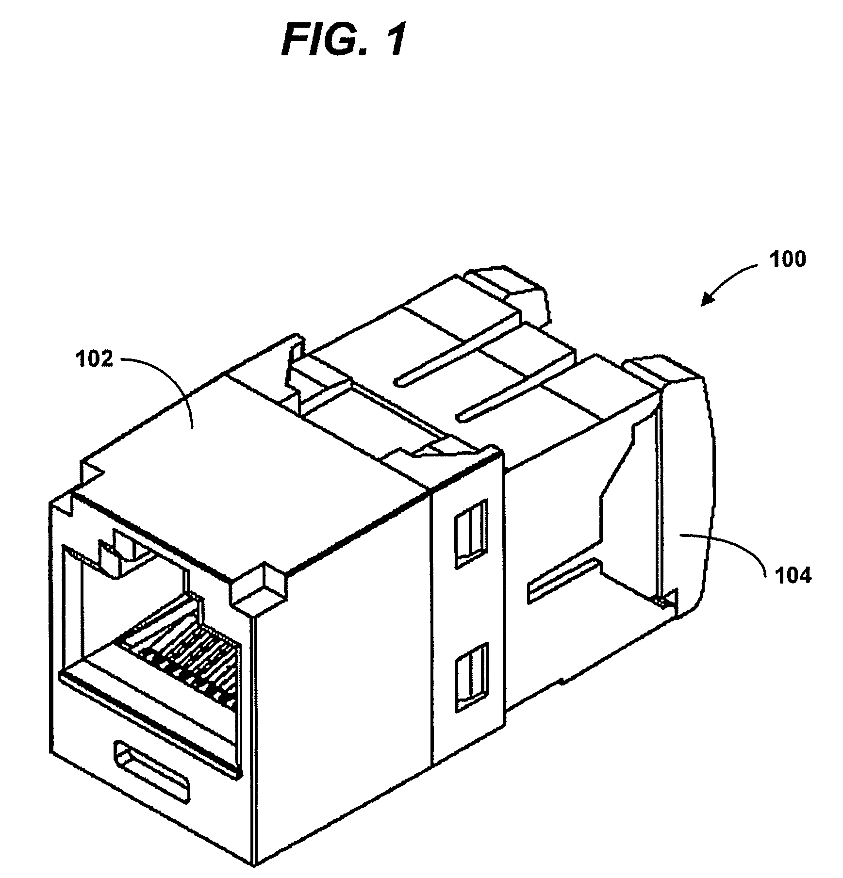
[0021]FIG. 1 is a front upper right perspective view of a communication jack 100 in accordance with an embodiment of the present invention. The communication jack 100 includes a front portion 102 and a wire containment cap 104. The front portion 102 may include such components as plug interface contacts, a mechanism for coupling the jack to a plug, crosstalk compensation circuitry, and wire-displacement contacts to provide an electrical connection between the jack and a communication cable. Additional details on the wire containment cap 104 are described with reference to FIGS. 3-7, below.

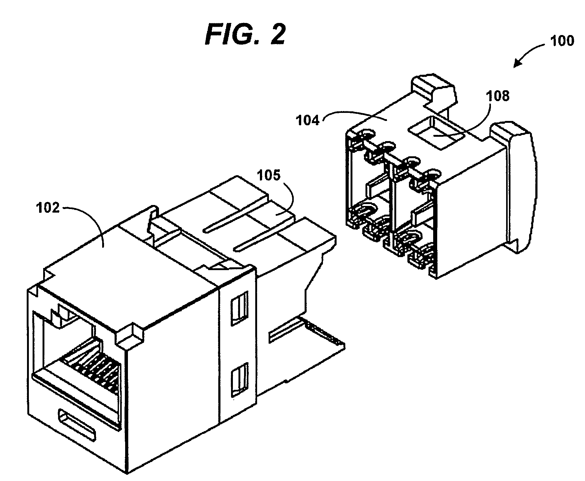
[0022]FIG. 2 is a front upper right partial-exploded view of the communication jack 100 of FIG. 1. In the embodiment shown, the wire containment cap 104 is slidably mounted within the front portion 102. A retention clip 105 on the front portion 102 and a retention recess 108 on the wire containment cap 104 may be included to secure the wire containment cap 104 to the front portion 102. Other mounti...


PUM


Abstract

A wire containment cap includes a first side having a plurality of retainers for retaining wires, and a second side opposite the first side. Two sidewalls extend between the first side and the second side, and a support rib extends between the two sidewalls. The support rib includes two pair separators for separating wire pairs. In one embodiment, a plurality of sloped pair splitters is located between two of the retainers and includes a sharp point for cutting through insulation material on a pair of bonded wires. A communication jack assembly including a front portion and the wire containment cap is also described.

Description

CROSS-REFERENCE TO RELATED APPLICATIONS[0001]This application claims the benefit of U.S. Provisional Application No. 60 / 598,640, filed Aug. 4, 2004 and U.S. Provisional Application No. 60 / 637,247, filed Dec. 17, 2004.[0002]Both of these applications are incorporated herein by reference in their entireties.FIELD OF THE INVENTION[0003]The present invention relates generally to electrical connectors, and more particularly, to a modular communication jack design with an improved wire containment cap.BACKGROUND OF THE INVENTION[0004]In the communications industry, as data transmission rates have steadily increased, crosstalk due to capacitive and inductive couplings among the closely spaced parallel conductors within the jack and / or plug has become increasingly problematic. Modular connectors with improved crosstalk performance have been designed to meet the increasingly demanding standards. Many of these connectors have addressed crosstalk by compensating at the front end of the jack, i...

Claims


Application Information

Patent Timeline
Patent Type & Authority Patents(United States)
IPC IPC(8): H01R24/00H01R24/58
CPCH01R13/6463H01R4/2433H01R24/64H01R13/58
Inventor DOORHY, MICHAEL V.BOLOURI-SARANSAR, MASUDPATEL, SATISH I.DYLKIEWICZ, DAVID A.
Owner PANDUIT
Why Eureka
Try Eureka