Leaflike shaft of a hip-joint prosthesis for anchoring in the femur

a technology of femur and leg, which is applied in the field of leglike shaft of a hip joint prosthesis for anchoring in the femur, can solve the problems of poor growth of bone tissue into the bone, and achieve the effect of revascularizing bone tissue and the necessary stability or solidity of the leg sha

Inactive Publication Date: 2008-11-25
SMITH & NEPHEW ORTHOPAEDICS
View PDF60 Cites 16 Cited by
  • Summary
  • Abstract
  • Description
  • Claims
  • Application Information

AI Technical Summary

Benefits of technology

[0008]The object of the present invention is to configure the femur-anchoring section of a leaflike shaft in such a way that the tissue growing onto the prosthesis consists to the greatest possible extent of spongy bone tissue, so as to ensure long-term, firm retention of the shaft in the femur.
[0019]These profiles all exhibit, to a greater or lesser extent, the property that in the space between the anchoring section of the shaft and the wall of the surgically created cavity spongy bone tissue forms, so that revascularization of the bone occurs. The alternatives in accordance with the invention have the advantage that their periphery comprises substantially four edges, situated at the corners of a rectangle or trapezoid that extends perpendicular to the central axis of the shaft. This basic shape of the shaft has been found in practice to be particularly advantageous for the revascularization of the bone tissue.

Problems solved by technology

However, bone tissue grows poorly into these.

Method used


Image

  • Leaflike shaft of a hip-joint prosthesis for anchoring in the femur
  • Leaflike shaft of a hip-joint prosthesis for anchoring in the femur
  • Leaflike shaft of a hip-joint prosthesis for anchoring in the femur

Examples


Embodiment Construction

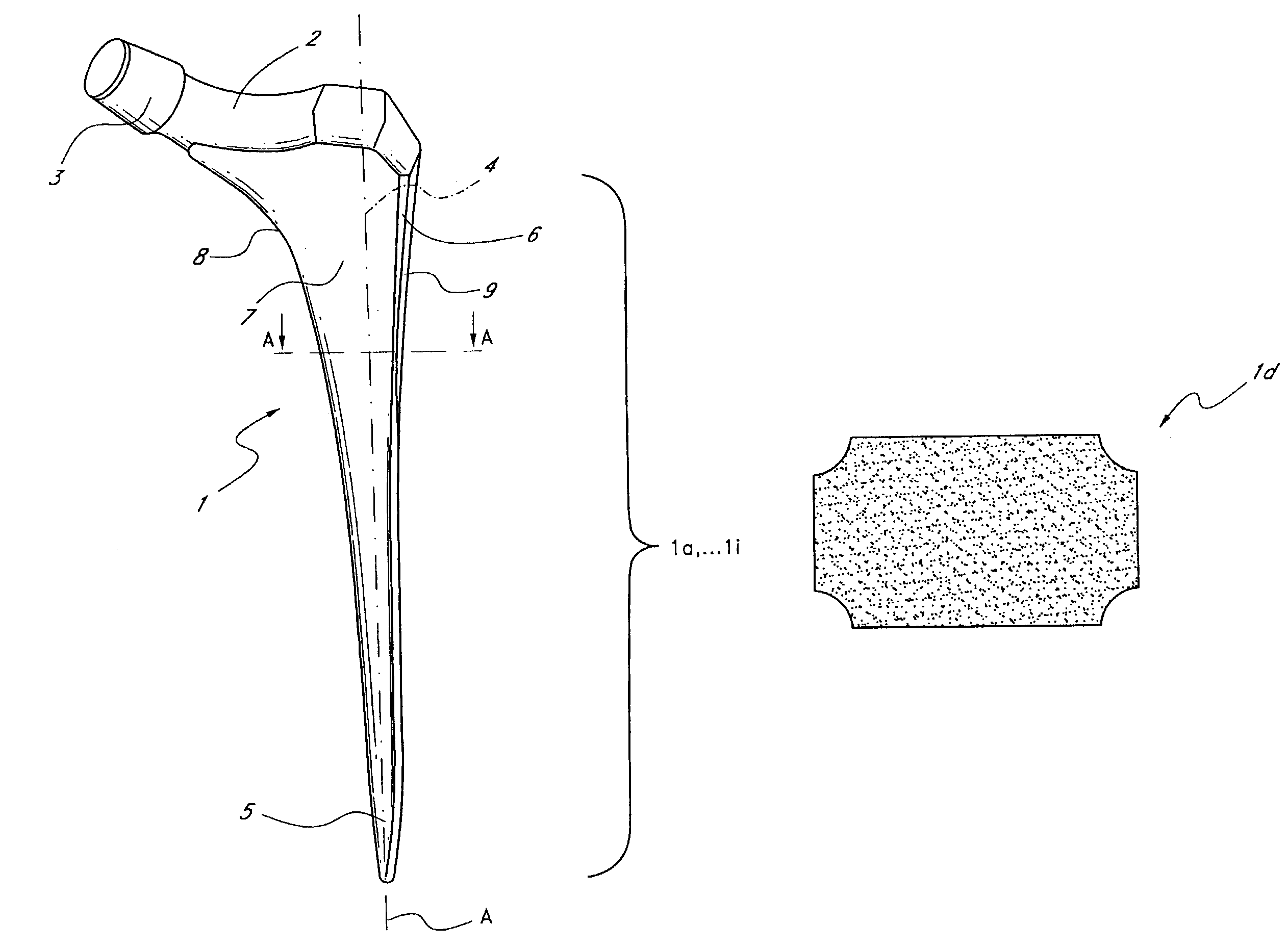
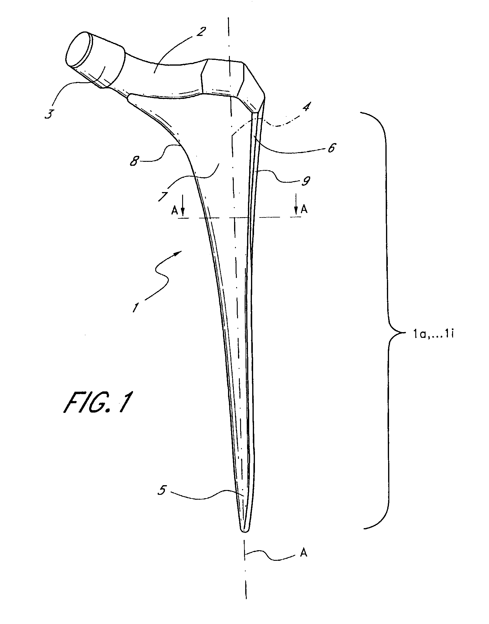
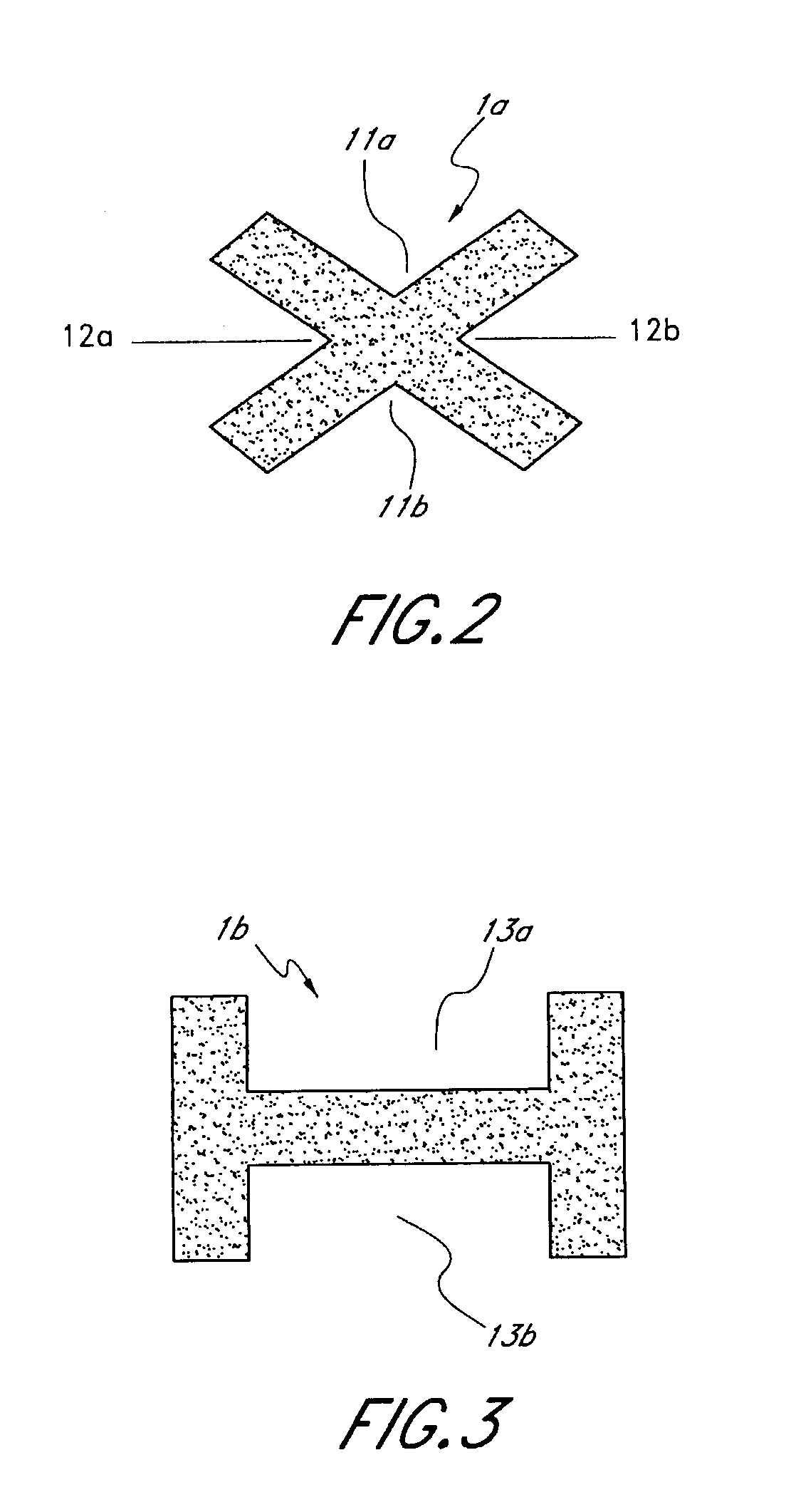
[0026]FIG. 1 shows, in perspective, a leaf-like shaft 1 of a hip-joint prosthesis for anchoring in the femur. The exemplary embodiment shown here comprises an anchoring section 1a, . . . 1i (see FIGS. 2 to 10), which expands conically on all sides from a distal end 5 to the proximal region, where on the medial side it merges with a continuously curving arch 8. This arch 8 is continuous with a prosthesis neck 2, onto which is set a conically tapering peg 3 which receives a spherical joint head. The prosthesis neck axis intersects the central long axis (not shown in FIG. 1) of the shaft and the anchoring section 1a . . . 1a at an angle that corresponds substantially to the angle between the neck and axis of the femur in a natural hip joint.

[0027]Laterally in the proximal region of the shaft 1 a trochanter wing 4 is formed, which is laterally delimited by a side surface 9. The transition between the lateral surface and the posterior or anterior surface is defined by a slanted edge 6 th...


PUM


Abstract

Leaflike shaft (1) of a hip-joint prosthesis for anchoring in the femur, according to a towards a distal end (5), with a femur-anchoring section (1a, . . . 1i) having a long axis (A) and with a prosthesis neck (2), wherein the femur-anchoring section (1a, . . . 1i) has a substantially rectangular external contour in a plane perpendicular to the long axis (A), optionally with recesses in the side edges and / or at the corners.

Description

CROSS-REFERENCE TO RELATED APPLICATIONS[0001]This application is a continuation application of U.S. patent application Ser. No. 10 / 355,385, filed on Jan. 30, 2003, now U.S. Pat. No. 7,175,668, which is a divisional of U.S. patent application Ser. No. 09 / 548,166, filed on Apr. 13, 2000, now U.S. Pat. No. 6,540,788.BACKGROUND OF THE INVENTION[0002]1. Field of the Invention[0003]The invention relates to a leaf-like shaft of a hip-joint prosthesis for anchoring in the femur, with a femur-anchoring section and a prosthesis neck.[0004]2. Description of the Related Art[0005]Profiled shafts of this kind are generally known. As only a few examples in this regard reference is made to the patents EP 0 427 902 B1 or EP 0 244 610 B1 or U.S. Pat. No. 4,908,035.[0006]As a rule the anchoring section of a shaft of the kind in question here is constructed with smooth surfaces. In EP 0 427 902 B1 it is proposed to construct one section of the shaft with contact surfaces provided with saw teeth. This m...

Claims


Application Information

Patent Timeline
Patent Type & Authority Patents(United States)
IPC IPC(8): A61F2/32A61F2/36A61B17/16A61F2/00A61F2/30
CPCA61F2/3662A61F2002/30535A61F2250/0058
Inventor ZWEYMULLER, KARL
Owner SMITH & NEPHEW ORTHOPAEDICS
Why Eureka
Try Eureka