Magnetic connector for mobile electronic devices

a technology of magnetic connectors and electronic devices, applied in the direction of coupling device connection, coupling parts engagement/disengagement, electrical apparatus, etc., can solve the problems of increasing the chance that the user tries to connect a cable to the wrong connector on the phone, the phone is dragged from the desk, and the phone is likely to get damaged

Active Publication Date: 2008-12-23
NOKIA TECH OY
View PDF15 Cites 130 Cited by
  • Summary
  • Abstract
  • Description
  • Claims
  • Application Information

AI Technical Summary

Benefits of technology

[0003]On this background, it is an object of the present invention to provide a connector for connecting a cable to a mobile electronic device that overcomes or at least reduces the disadvantages associated with the conventional connectors described above.
[0005]The magnetically established mechanical connection can be disengaged with relatively low forces, thereby ensuring that the mobile electronic device will not be dragged away when the cable is pulled. Thus, when the user forgets to disengage his earphones or his battery charger and walks away the connection between the respective cable and the mobile electronic device will be broken without the mobile electronic device being dragged from its place, or without excessive force is being applied to the cable and the electronic device.

Problems solved by technology

The close spacing that is required for keeping the mobile devices increases the chance that the user tries to connect a cable to the wrong connector on the phone.
For example when a user has put his phone on a desk and walks away wearing his earphones this will cause the phone to be dragged from the desk and the phone will possibly get damaged by the impact that follows the fall from the desk.

Method used


Image

  • Magnetic connector for mobile electronic devices
  • Magnetic connector for mobile electronic devices
  • Magnetic connector for mobile electronic devices

Examples


second embodiment

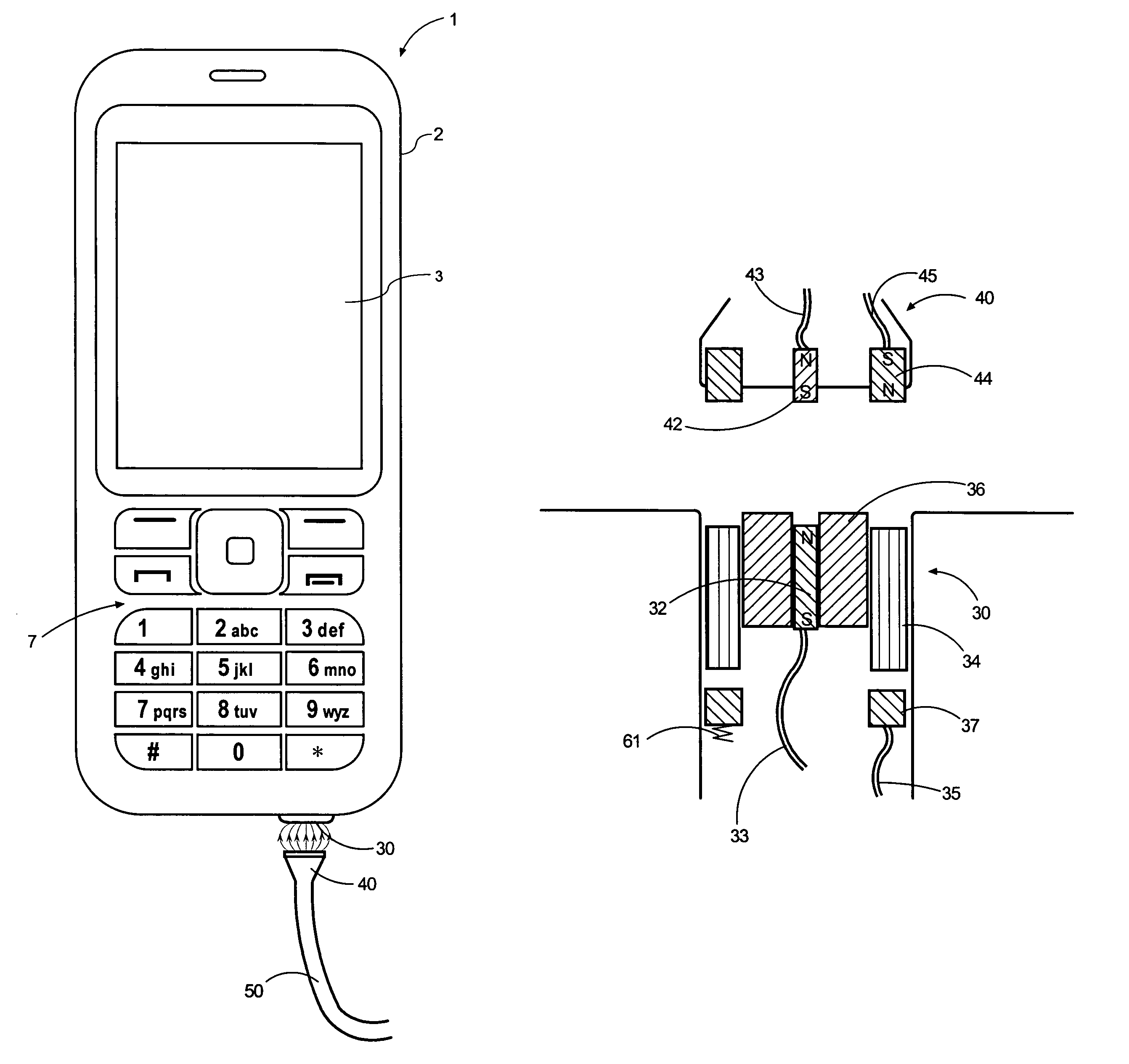
[0034]FIG. 6 shows the invention in which the mobile electric device 1 is provided with two connector parts. Connector part 30a includes a permanent bar magnet 32b that is oriented with its magnetic south pole towards its contact surface 33a. Connector part 30b includes a permanent bar magnet 32b that is oriented with its magnetic north pole towards its contact surface 33b. The contact surfaces 33a and 33b are provided with electrical contacts (not shown) which are connected to electrical wiring (not shown) leading to the electronic components inside the mobile electric device 1.

[0035]A cable 50a is provided at its end with a connector part 40a. Another cable 50b is provided at its end with a connector part 40b. The cables 50a and 50b are different cables with different functions such as for example a charging cable 50a and a cable 50b for connecting the mobile electric device 1 to a personal computer. The connector part 40a includes a bar magnet 42a that is oriented with its magnet...

fourth embodiment

[0038]FIGS. 7 and 8 show the connector according to the present invention. The connector includes a connector part 130 that is by way of example disposed in the mobile electronic device 1, and connector parts 140a and 140b that are by way of example connected to respective cables (not shown).

[0039]Connector part 140a includes a plate magnet 142a that is disposed in the connector part 140a with its magnetic south pole towards the contact side of the connector 140a. The connector 140a includes three concentrically disposed electrical contacts 143, 144 and 145, that are separated by insulating bushings. The electrical contact 145 is disposed at the bottom of a central cylindrical recess formed in the front surface of the connector. The recess serves to receive a cylindrical projection formed by electrical contact 135 that is protruding from the contact surface of the connector part 130. The electrical contacts 143,144 and 145 are connected to wires (not shown) in the cable that is atta...


PUM


Abstract

A magnetic connector for connecting various cables to a mobile electronic device includes a connector part in the mobile electronic device and a connector part attached to the cable. One of the connector parts includes a permanent magnet and the other connector part includes magnetic material or another magnet. The attractive magnetic force between the permanent magnet or the other magnet and the magnetic material keeps the connector parts into engagement. The magnets may themselves form the electrical contacts. The connector parts can also include magnetically operated switches.

Description

FIELD OF THE INVENTION[0001]The present invention relates to connectors for connecting a cable to a mobile electronic device, in particular to releasable connectors.BACKGROUND OF THE INVENTION[0002]Mobile electronic devices, such as mobile phones, are usually provided with a plurality of connectors to allow the mobile phone to be connected to a cable of a battery charger, to a cable of earphones, or to a cable for connecting the mobile phone to a personal computer. Typically, there are several closely spaced separate connectors located in an area of the phone. The close spacing that is required for keeping the mobile devices increases the chance that the user tries to connect a cable to the wrong connector on the phone. Further, many of the connectors that are presently used in mobile phones are similar to jacks or plugs and constitute openings in the phone that can collect dust and dirt. In most of the connector types used, the engagement between the connecting parts is ensured by ...

Claims


Application Information

Patent Timeline
Patent Type & Authority Patents(United States)
IPC IPC(8): H01R11/30
CPCH01R13/6205H01R13/70H01R13/7037H01R2201/16H01R11/30H01R13/62
Inventor LINDBERG, PHILLIPSHIRGAONKAR, SAMEERBJORNINEN, KATI
Owner NOKIA TECH OY
Why Eureka
Try Eureka